Paragraphs 117-119
PARK BRAKE
Aii iModeis
117.
A Ught duty park brake is used on Models 385
and 485 equipped with two-wheel drive. Park brake
drum is located on the bevel drive pinion (range
transmission mainshaft). Refer to paragraph 112 of
the RANGE TRANSMISSION section for R&R
procedures.
A heavy duty park brake is used on Models 585,
685 and 885 equipped with two-wheel drive and aU
models equipped with four-wheel drive. The park
brake drum is the flange on the bevel ring gear. Re-
fer to paragraph 115 for R&R procedures.
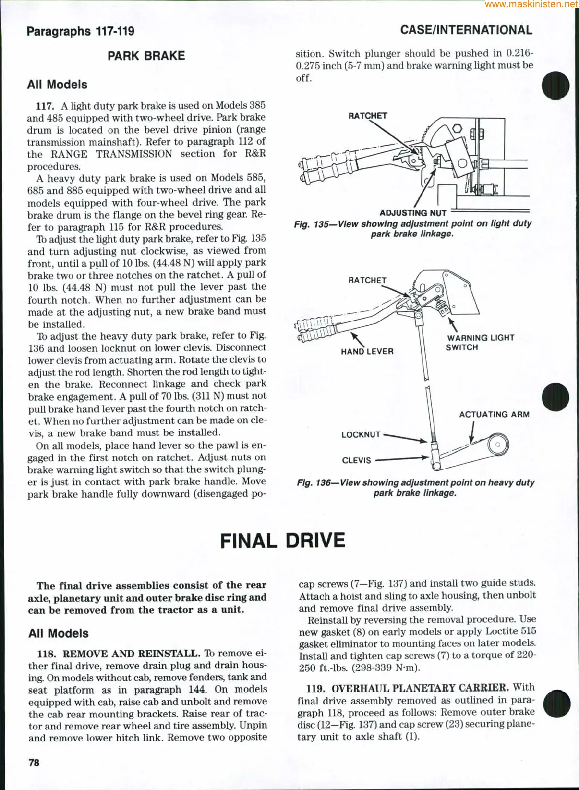
Ib adjust the Ught duty park brake, refer to
Fig.
135
and turn adjusting nut clockwise, as viewed from
front, until a puU of 10 lbs. (44.48 N) wiU apply park
brake two or three notches on the ratchet. A puU of
10 lbs. (44.48 N) must not puU the lever past the
fourth notch. When no further adjustment can be
made at the adjusting nut, a new brake band must
be installed.
Ib adjust the heavy duty park brake, refer to Fig.
136 and loosen locknut on lower clevis. Disconnect
lower clevis from actuating arm. Rotate the clevis to
adjust the rod length. Shorten the rod length to tight-
en the brake. Reconnect Unkage and check park
brake engagement. A puU of 70 lbs. (311 N) must not
puU brake hand lever past the fourth notch on ratch-
et. When no further adjustment can be made on cle-
vis,
a new brake band must be instaUed.
On all models, place hand lever so the pawl is en-
gaged in the first notch on ratchet. Adjust nuts on
brake warning light switch so that the switch plung-
er is just in contact with park brake handle. Move
park brake handle fully downward (disengaged po-
CASE/iNTERNATiON AL
sition. Switch plunger should be pushed in 0.216-
0.275 inch (5-7 mm) and brake warning light must be
off.
RATCHET
ADJUSTING NUT
Fig. 135—View showing adjustment point on light duty
park brake iinkage.
RATCHET
HAND LEVER
WARNING LIGHT
SWITCH
ACTUATING ARM
LOCKNUT
CLEVIS
Fig. 136—View showing adjustment point on heavy duty
park brake iinkage.
FINAL DRIVE
The final drive assemblies consist of the rear
axle, pianetary unit and outer brake disc ring and
can be removed from the tractor as a unit.
Aii iModeis
118.
REMOVE AND REINSTALL. Ib remove ei-
ther final drive, remove drain plug and drain hous-
ing. On models without
cab,
remove fenders, tank and
seat platform as in paragraph 144. On models
equipped with cab, raise cab and unbolt and remove
the cab rear mounting brackets. Raise rear of trac-
tor and remove rear wheel and tire assembly. Unpin
and remove lower hitch Unk. Remove two opposite
cap screws (7—Fig. 137) and instaU two guide studs.
Attach a hoist and sling to axle housing, then unbolt
and remove final drive assembly.
ReinstaU by reversing the removal procedure. Use
new gasket (8) on early models or apply Loctite 515
gasket eUminator to mounting faces on later models.
InstaU and tighten cap screws (7) to a torque of 220-
250 ft.-lbs. (298-339 N-m).
119.
OVERHAUL PLANETARY CARRIER. With
final drive assembly removed as outlined in para-
graph 118, proceed as follows: Remove outer brake
disc (12-Fig. 137) and cap screw (23) securing plane-
tary unit to axle shaft (1).
78
 Loading...


