SERVICE MANUAL
Paragraph 116
cap screws (17) evenly until a slight amount of end
play can be felt at ring gear Remove sling and hoist
from differential. Rotate differential several turns to
make sure carrier bearings are seated. Wind a cord
around the differential lock ring (14) and connect a
spring scale to end of cord. Make certain that range
gears are in neutral position. Pull the spring scale and
note the amount of pull required to rotate the
differential assembly. Then, continue tightening left
side cap screws evenly to a torque of 115430 ft.-lbs.
(156-176
N'm).
Again, using the spring scale and cord,
check amount of pull needed to rotate the differen-
tial assembly. The bearing preload is correct when
a rolling pull on scale is 4.5-14.5 lbs. (2.0-6.5 kg). Add
or remove shims as required to obtain correct amount
of pull. One shim thickness of
0.001
inch (0.025 mm)
will change amount of puU 1.0
lb.
(0.64 kg). Shims are
available in thicknesses of 0.003, 0.007, 0.012 and
0.030 inch (0.076, 0.170, 0.300 and 0.760 mm).
NOTE:
Always support the differential assembly
when removing the bearing housings.
With bearing preload set, adjust bevel gear back-
lash as follows: Support differential assembly and re-
move bearing housings
(18
and 22). Divide the shims
and install half on each bearing housing. Install right
bearing housing (18) and tighten cap screws to a
torque of 115-130 ft.-lbs. (156476 N-m). Install left
bearing housing (22) and tighten left side cap screws
to a torque of 115-130 ft.-lbs. (156-176
N-m).
Make sure
some backlash exists between bevel ring gear
(6)
and
bevel drive pinion (5). Using a dial indicator, check
backlash. Backlash should be 0.006-0.012 inch
(0.15-
0.30 mm). Check backlash every 90 degrees of ring
gear. Backlash must not vary more than 0.004 inch
(0.1 mm) during the four readings. Tb increase back-
lash, remove shims from right side and install on left
side,
lb decrease backlash, remove shims from left
side and install on right side. Do not change total
number of shims as this will affect bearing preload.
Shim pack thickness must not be more than 0.071
inch (1.80 mm) on either side.
With bearing preload and backlash adjusted, re-
move bearing housings and install new "O*' rings (19
and 20). Lubricate '*0'* rings with petroleum jelly.
Apply Loctite
241
to bearing housing cap screws (17),
then tighten cap screws to a torque of 115-130 ft.-lbs.
(156-176 N-m).
Lubricate new
**0"
rings with petroleum jelly and
install on brake pistons. Install brake pistons, then
install brake inner rings. The balance of reassembly
is the reverse of disassembly procedures.
DIFFERENTIAL LOCK
All tractors are equipped with a differential
lock which operates on the right side of the
differential with a dowel pin type coupling lock-
ing the differential gears. It is operated with a
pedal on right side of tractor.
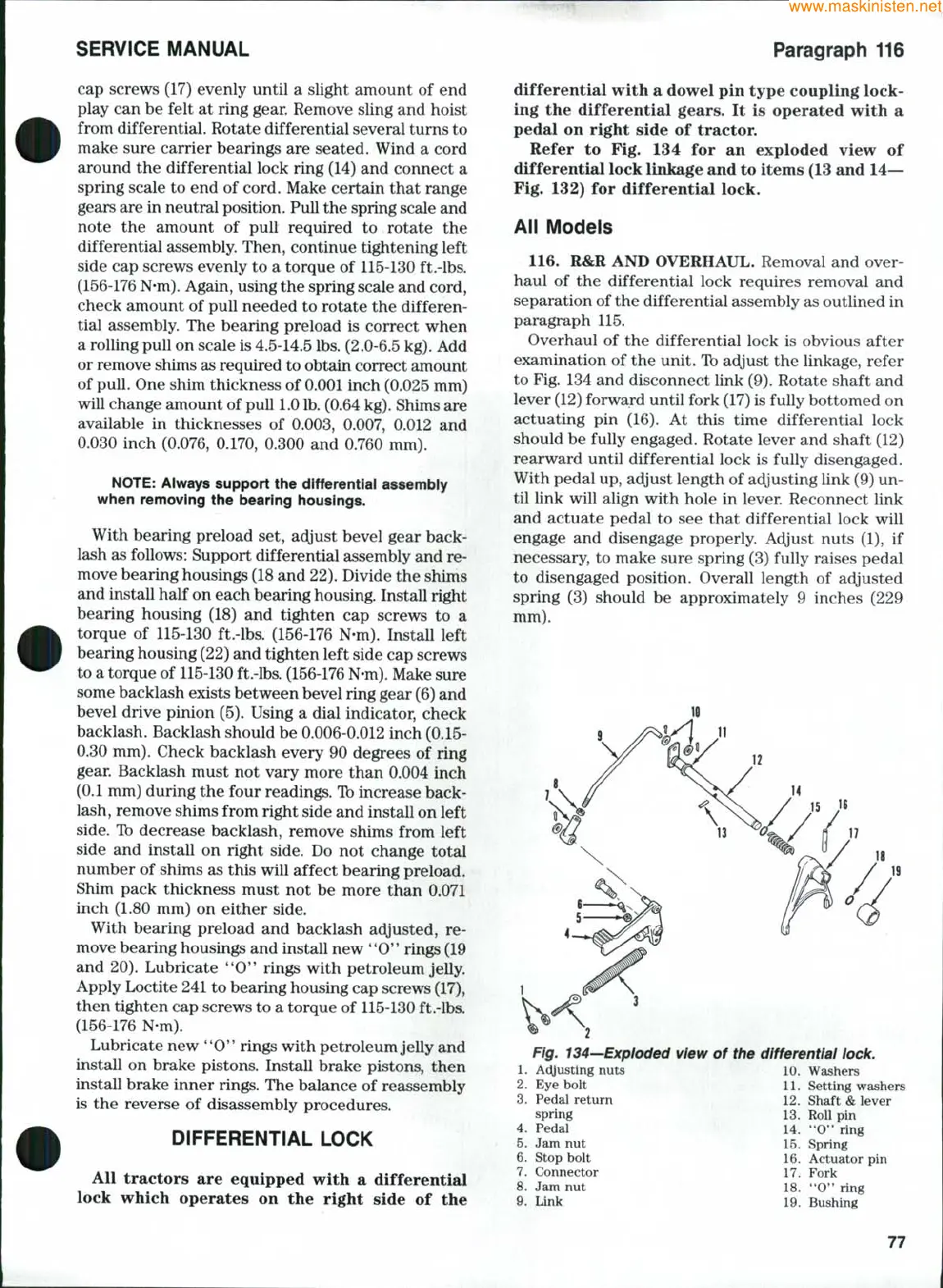
Refer to Fig. 134 for an exploded view of
differential lock linkage and to items (13 and 14—
Fig. 132) for differential lock.
All Models
116.
R&R AND OVERHAUL. Removal and over-
haul of the differential lock requires removal and
separation of the differential assembly as outlined in
paragraph 115.
Overhaul of the differential lock is obvious after
examination of the unit. Tb adjust the linkage, refer
to Fig. 134 and disconnect link (9). Rotate shaft and
lever (12) forward until fork (17) is fully bottomed on
actuating pin (16). At this time differential lock
should be fully engaged. Rotate lever and shaft (12)
rearward until differential lock is fully disengaged.
With pedal up, adjust length of adjusting link (9) un-
til link will align with hole in lever. Reconnect link
and actuate pedal to see that differential lock will
engage and disengage properly. Adjust nuts (1), if
necessary, to make sure spring (3) fully raises pedal
to disengaged position. Overall length of adjusted
spring (3) should be approximately 9 inches (229
mm).
Fig. 134—Exploded view of the differential
lock.
1.
Actjusting nuts 10. Washers
2.
Eye bolt 11. Setting washers
3.
Pedal return 12. Shaft & lever
spring 13. Roll pin
4.
Pedal ; 14. "0" ring
5.
Jam nut 15. Spring
6. Stop bolt 16. Actuator pin
7.
Connector 17. Fork
8. Jam nut 18. "0" ring
9. Link 19. Bushing
77
 Loading...


