Paragraph 115 (Cont.)
CASE/iNTERNATiONAL
drives as in paragraph 118. Disconnect and remove
bevel pinion and ring gear lubrication tube. Discon-
nect and remove differential lock shaft and fork. On
models so equipped, disconnect and remove heavy
duty park brake cam pivot and brake band hanger
support. On
aU
models, remove inner brake ring from
each side. Refer to Fig. 131 and using special tool IH
7847A and a sUde hammer, puU out brake pistons. In-
staU a rope through differential carrier for a sUng and
attach it to a hoist. Support differential with the hoist
and unbolt and remove bearing housings (18 and
22—Fig. 132) and shims
(21).
Identify and keep shims
with their relevant bearing housing. Remove differen-
tial and heavy duty park brake band, if so equipped.
See Fig. 133. Slip off the brake band.
Remove bolts
(3
and
4—Fig.
132) and separate bevel
ring gear (6) from differential carrier (11). Remove
thrust washer (7).
NOTE:
The four dowel bolts (3) secure the four
stub shafts (10). On Models 385 and 485, single
cross shaft (12) and two pinions (9) are used.
Remove stub shafts (10) or cross shaft
(12),
then re-
move side gears (8) and differential pinions (9). Us-
ing a suitable puUer, remove bearing cones
(2
and 15).
Remove differential lock ring (14) and springs (13).
If necessary, remove bearing cups (1 and 16) from
bearing housings (18 and 22).
Clean and inspect all parts and renew any show-
ing excessive wear or other damage. If bevel ring gear
is to be renewed, bevel pinion shaft (5) must also be
renewed as they are available only as a matched set.
Refer to paragraphs 111, 112 or 113 for instaUation
and position adjustment of the bevel pinion shaft.
Reassemble by reversing the disassembly procedure
keeping the following points in mind: Thrust washer
(7) has a lug which locates in a hole in bevel ring gear.
Use petroleum jelly to stick thrust washer in ring gear
for aid in installation to differential carrier. Use Loc-
tite
241
on threads of bolts
(3
and 4) and tighten bolts
to a torque of 115-130 ft.-lbs. (156-176 N-m).
Reinstall differential and adjust carrier bearing
preload as follows: Install right bearing housing (18)
without shims (21) and
**0"
rings (19 and 20). Tight-
en cap screws (17) evenly to a torque of 115-130 ft.-
lbs.
(156-176 N-m). InstaU left bearing housing (22)
without
*
*0"
rings (19 and 20) but with
aU
shims (21)
removed from right and left sides. Tighten left side
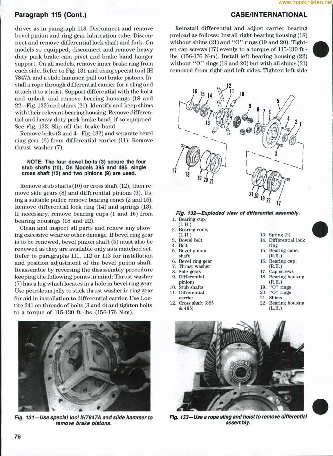
Fig. 132—Exploded view of differentiai assembly.
1.
Bearing cup,
(L.H.)
2.
Bearing cone,
(L.H.)
3.
Dowel bolt
4.
Bolt
5.
Bevel pinion
shaft
6. Bevel ring gear
7.
Thmst washer
8. Side gears
9. Differential
pinions
10.
Stub shafts
11.
Differential
carrier
12.
Cross shaft (385
&485)
13.
Spring (2)
14.
Differential lock
ring
15.
Bearing cone,
(R.H.)
16.
Bearing cup,
(R.H.)
17.
Cap screws
18.
Bearing housing,
(R.H.)
19.
**0" rings
20.
"0" rings
21.
Shims
22.
Bearing housing.
(L.H.)
Fig. 131—Use speciai tool IH7847A and slide hammer to
remove brake pistons.
Fig.
133—Use
a rope
sling
and
hoist to remove differential
assembly.
76
 Loading...


