SERVICE MANUAL
Paragraphs 122-123
right angle from foot plate. Tighten locknut. Loosen
right pedal adjuster locknut and turn pivot bolt to
set ri^t pedal 8-1/4 inches (210 mm) from foot plate.
Check to see that pedal lock will engage easily. If not,
adjust right pedal until lock engages easily. Tighten
locknut. Install right side panel.
Ib a(yust the pedal height on models equipped with
cab,
remove hood and grille assembly. Remove rear
side panels and instrument panel front cover. Discon-
nect battery cables, then unbolt and raise instrument
panel as necessary. Refer to Fig. 142 and loosen lock-
nut at clevis on both
pedals.
Remove clevis
pins.
Loos-
en locknuts on stop bolts and turn stop bolts coun-
terclockwise several turns. Pull both clevises free
from pedals and adjust each clevis to obtain the cor-
rect pedal height of 7-7/8 to 8-1/8 inches (199-205
mm).
Install clevis pins. Check to see that both pe-
dals are of equal height and that pedal lock will en-
gage easily. If not, readjust left pedal height to cor-
rect. Press each pedal down 1/4 inch (6 mm) and
check to see that there is a slight amount of free play
at the push rods. If not, turn clevis 1/2 turn counter-
clockwise. Tighten clevis locknuts. Turn pedal stop
bolts clockwise until they contact pedals, then turn
clockwise 1/4 of a turn and tighten locknuts.
BLEED BRAKES
All Models
122.
Ib bleed air from brakes, start tractor and let
it run for a few minutes to ensure the brake lines are
filled. Keep engine operating while bleeding brakes.
Clamp brake return hose to the transmission to pre-
vent return oil flow. Attach two plastic hoses 1/4 inch
(6 mm) ID x 30 inches (76.2 cm) long over brake
bleeder fittings. Run opposite end of hoses into the
transmission filler plug hole. Loosen both air removal
screws one full turn. Start engine and operate at low
idle speed. Make sure brake pedals are latched to-
gether. Press pedals down quickly and release slow-
ly. Continue until fluid with no air bubbles flows from
hoses.
Tighten left air remove screw and unlatch pedals.
Hold right pedal half way down. Press left pedal
down quickly and release slowly until fluid with no
air bubbles flows from right air removal hose. Tight-
en right air removal screw and loosen left screw one
full turn. Hold left pedal half way down. Press right
pedal down quickly and release slowly until fluid
with no air bubbles flows from left air removal hose.
Tighten left air removal screw. Remove clamp from
brake return hose.
Latch pedals together and check operation of
brakes. If brakes feel soft, repeat bleeding operation.
Remove bleed hoses and install transmission filler
plug.
BRAKE ASSEMBLIES
All Models
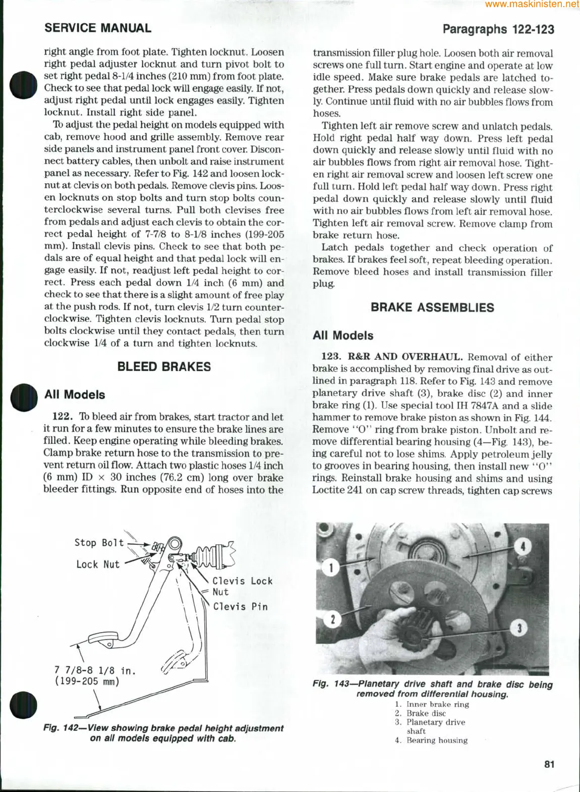
123.
R&R AND OVERHAUL. Removal of either
brake is accomplished by removing final drive as out-
lined in paragraph 118. Refer to Fig. 143 and remove
planetary drive shaft (3), brake disc (2) and inner
brake ring (1). Use special tool IH 7847A and a slide
hammer to remove brake piston as shown in Fig, 144.
Remove **0" ring from brake piston. Unbolt and re-
move differential bearing housing (4—Fig, 143), be-
ing careful not to lose shims. Apply petroleum jelly
to grooves in bearing housing, then install new '*0"
rings.
Reinstall brake housing and shims and using
Loctite 241 on cap screw threads, tighten cap screws
Stop Bolt
Lock Nut
7 7/8-8 1/8 in.
(199-205 mm)
Clevis Lock
Nut
Clevis Pin
Fig. 142—View showing brake pedal height adjustment
on all models equipped with cab.
drive shaft and brake disc being
removed from differential housing.
Inner brake ring
Brake disc
Planetary drive
shaft
Bearing housing
81