Paragraphs 81-62
CASE/iNTERNATiONAL
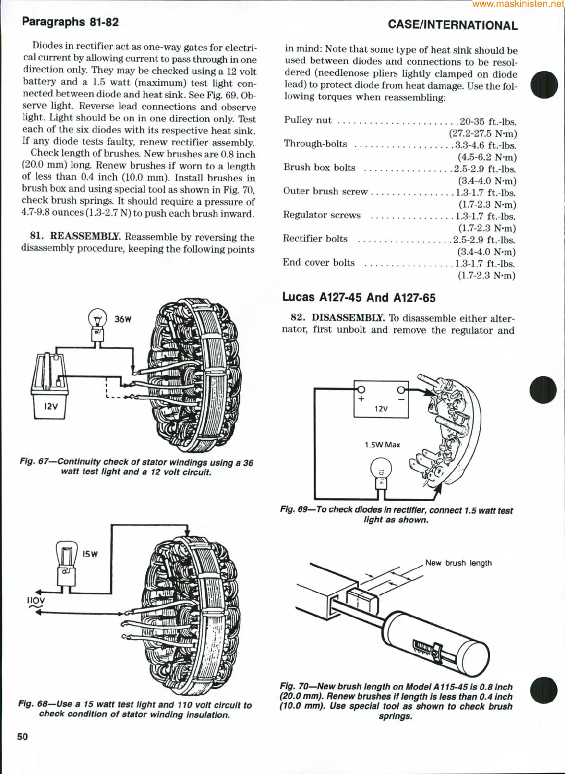
Diodes in rectifier act as one-way gates for electri-
cal current by allowing current to pass through in one
direction only. They may be checked using a 12 volt
battery and a 1.5 watt (maximum) test light con-
nected between diode and heat sink. See
Fig.
69. Ob-
serve light. Reverse lead connections and observe
light. Light should be on in one direction only. Ibst
each of the six diodes with its respective heat sink.
If any diode tests faulty, renew rectifier assembly.
Check length of
brushes.
New brushes are 0.8 inch
(20.0 mm) long. Renew brushes if worn to a length
of less than 0.4 inch (10.0 mm). Install brushes in
brush box and using special tool as shown in Fig. 70,
check brush springs. It should require a pressure of
4.7-9.8 ounces (1.3-2.7 N) to push each brush inward.
81.
REASSEMBLSr. Reassemble by reversing the
disassembly procedure, keeping the following points
Fig.
67—Continuity
check of stator windings using a 36
watt test light and a 12 volt circuit.
iiOV
in mind: Note that some type of heat sink should be
used between diodes and connections to be resol-
dered (needlenose pliers lightly clamped on diode
lead) to protect diode from heat damage. Use the fol-
lowing torques when reassembling:
Pulley nut 20-35 ft.-lbs.
(27.2-27.5 N-m)
Through-bolts 3.3-4.6 ft.-lbs.
(4.5-6.2 N-m)
Brush box bolts 2.5-2.9 ft.-lbs.
(3.4-4.0 N-m)
Outer brush screw
1.3-1.7
ft.-lbs.
(1.7-2.3 N-m)
Regulator screws
1.3-1.7
ft.-lbs.
(1.7-2.3 N-m)
Rectifier bolts 2.5-2.9 ft.-lbs.
(3.4-4.0 N-m)
End cover bolts
1.3-1.7
ft.-lbs.
(1.7-2.3 N-m)
Lucas A127-45 And A127-65
82.
DISASSEMBiy. Ib disassemble either alter-
nator, first unbolt and remove the regulator and
Fig.
69—To check diodes
in
rectifier,
connect
1.5
watt test
iight as shown.
New brush length
Fig.
68—Use
a 15 watt test light and
110
volt circuit to
check condition of stator winding Insulation.
Fig.
70—New brush
length on
Model A115-45
is 0.8 inch
(20.0
mm).
Renew brushes
if
length
is iess than 0.4 inch
(10,0 mm). Use speciai tool as shown to check brush
springs.
50
 Loading...


