SERViCE MANUAL
Paragraph 83
brush holder assembly (1—Fig. 71). Place an align-
ment chalk mark across slip ring end frame (2), sta-
tor frame (10) and drive end frame (9). Remove the
three through-bolt nuts and lockwashers and sepa-
rate slip ring end frame (2) and stator
(10)
from drive
end frame and rotor. Remove nuts, washers and in-
sulators from stud terminals and the two screws
securing stator to rear frame, then remove stator. Un-
solder and remove stator leads from rectifier and sep-
arate rectifier from stator.
Remove pulley nut (5), lockwasher (6), pulley (7),
fan
(8),
spacer (16) and washer (15) from rotor shaft.
Remove rotor (11) and spacer (13) from drive end
frame (9) and bearing (14) assembly. If bearing (14)
is faulty, renew drive end frame assembly as bear-
ing is not serviced separately. If rear needle bearing
(3) is excessively worn, press out old bearing and
press in new bearing until flush with frame.
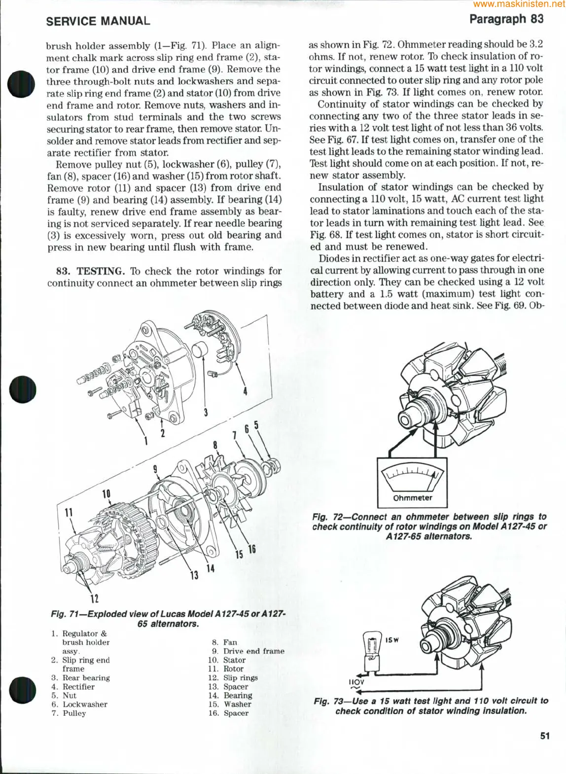
83.
TESTING. Ib check the rotor windings for
continuity connect an ohmmeter between slip rings
Fig. 71—Expioded view of Lucas Model Al 27-45 or Al 27-
1.
Regulator &
brush holder
assy.
2.
Slip ring end
frame
3.
Rear bearing
4.
Rectifier
5.
Nut
6. Lockwasher
7.
Pulley
65 alternators.
8. Fan
9. Drive end frame
10.
Stator
11.
Rotor
12.
Slip rings
13.
Spacer
14.
Bearing
15.
Washer
16.
Spacer
as shown in Fig. 72. Ohmmeter reading should be 3.2
ohms.
If not, renew rotor. Ib check insulation of ro-
tor windings, connect a
15
watt test light in a
110
volt
circuit connected to outer slip ring and any rotor pole
as shown in Fig. 73. If light comes on, renew rotor.
Continuity of stator windings can be checked by
connecting any two of the three stator leads in se-
ries with a 12 volt test light of not less than 36 volts.
See Fig. 67. If test light comes on, transfer one of the
test light leads to the remaining stator winding lead.
Test light should come on at each position. If not, re-
new stator assembly.
Insulation of stator windings can be checked by
connecting a 110 volt, 15 watt, AC current test light
lead to stator laminations and touch each of the sta-
tor leads in tum with remaining test light lead. See
Fig. 68. If test light comes on, stator is short circuit-
ed and must be renewed.
Diodes in rectifier act as one-way gates for electri-
cal current by allowing current to pass through in one
direction only. They can be checked using a 12 volt
battery and a 1.5 watt (maximum) test light con-
nected between diode and heat sink. See Fig. 69. Ob-
Fig. 72—Connect an ohmmeter between siip rings to
check continuity of rotor windings on Model A127-45 or
Al27-65 alternators.
IIOV
Fig. 73—Use a 15 watt test light and 110 voit circuit to
check condition of stator winding insuiation.
51
 Loading...


