Paragraph 126 (Cont.)
CASE/INTERNATIONAL
on gage should be 260-270 psi (1790-1860 kPa). If
reading is correct, there is no problem in hydraulic
system of the pto. If reading is not correct, remove
test gage and remove pressure line from MCV to tee
fitting. Cap tee fitting and connect test gage to the
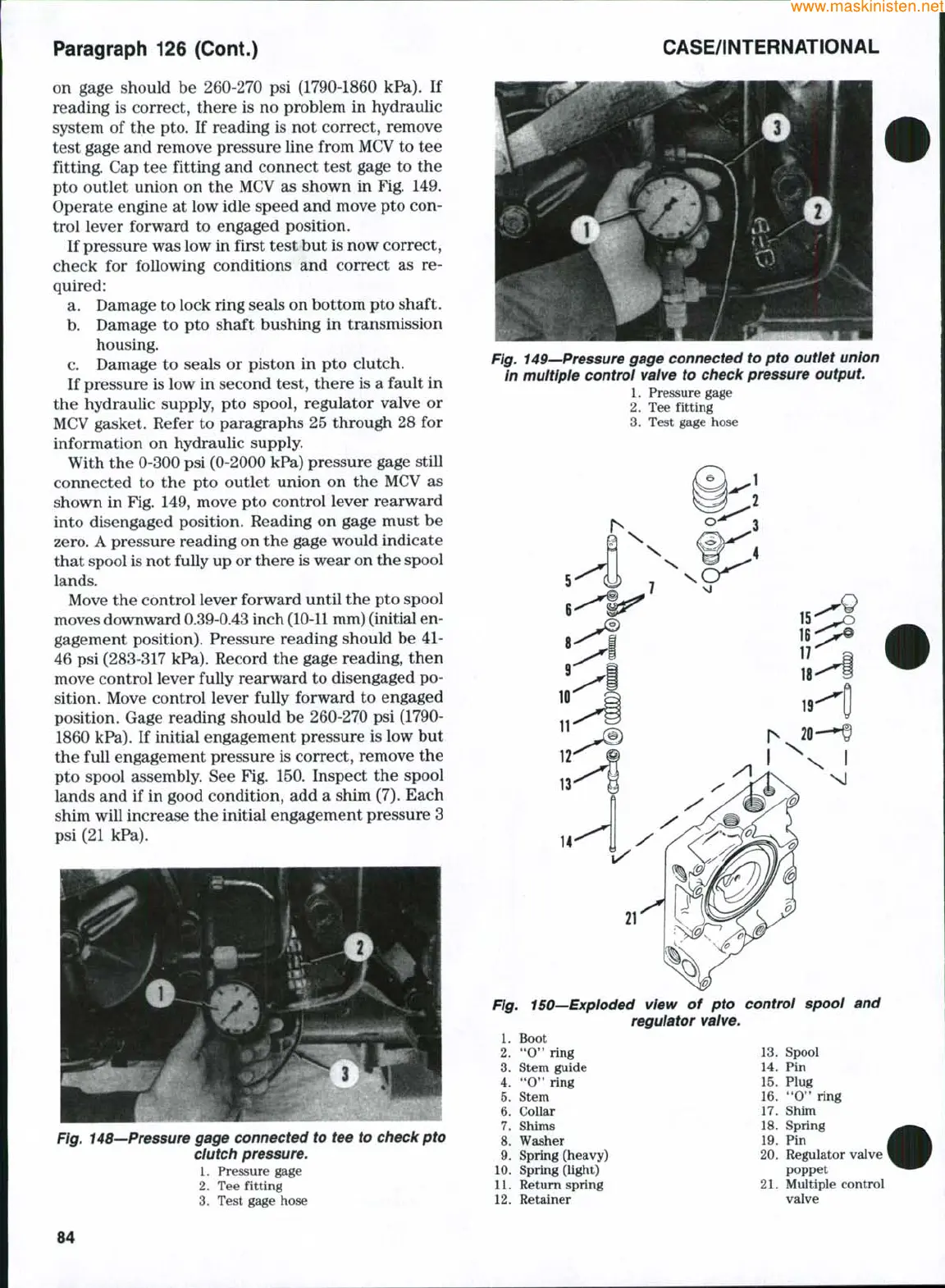
pto outlet union on the MCV as shown in Fig. 149.
Operate engine at low idle speed and move pto con-
trol lever forward to engaged position.
If pressure was low in first test but is now correct,
check for following conditions and correct as re-
quired:
a. Damage to lock ring seals on bottom pto shaft.
b.
Damage to pto shaft bushing in transmission
housing.
c. Damage to seals or piston in pto clutch.
If pressure is low in second test, there is a fault in
the hydraulic supply, pto spool, regulator valve or
MCV gasket. Refer to paragraphs 25 through 28 for
information on hydraulic supply.
With the 0-300 psi (0-2000 kPa) pressure gage still
connected to the pto outlet union on the MCV as
shown in Fig. 149, move pto control lever rearward
into disengaged position. Reading on gage must be
zero.
A pressure reading on the gage would indicate
that spool is not fully up or there is wear on the spool
lands.
Move the control lever forward until the pto spool
moves downward 0.39-0.43 inch
(10-11
mm) (initial en-
gagement position). Pressure reading should be 41-
46 psi (283-317 kPa). Record the gage reading, then
move control lever fully rearward to disengaged po-
sition. Move control lever fully forward to engaged
position. Gage reading should be 260-270 psi (1790-
1860 kPa). If initial engagement pressure is low but
the full engagement pressure is correct, remove the
pto spool assembly. See Fig. 150. Inspect the spool
lands and if in good condition, add a shim (7). Each
shim will increase the initial engagement pressure 3
psi (21 kPa).
Fig. 148—Pressure gage connected to tee to check pto
clutch pressure.
1.
Pressure gage
2.
Tee fitting -
3.
Test gage hose
Fig. 149—Pressure gage connected to pto outlet union
In multiple control valve to check pressure output.
1
Prpssiirp
ffasff^
1.
Pressure gage
2.
Tee fitting
3.
Test gage hose
14
Fig. 150—Exploded view of pto control spool and
regulator valve.
1.
Boot
ring
2.
3.
Stem guide
4.
**0*'
ring
5.
Stem
6. Collar
7.
Shims
8. Washer
9. Spring (heavy)
10.
Spring (light)
11.
Return spring
12.
Retainer
13.
Spool
14.
Pin
15.
Plug
16.
**0" ring
17.
Shim
18.
Spring
19.
Pin
20.
Regulator valve
poppet
21.
Multiple control
valve
84
 Loading...


