SECTION 7
WING
FLAP
CONTROL SYSTEM
T
ABLE
OF
CONTENTS
Page
WING
FLAP
CONTROL
SYSTEM.
Description
. . . . . . . .
Operational
Check
. . . . .
Trouble
Shooting . . . . . .
Flap
Motor
and
Transmission
Assembly
Removal
and
Installation
Repair
.......
.
Drive
Pulleys
. . . . . . .
Removal
and
Installation
Repair
........
.
7-1.
WING
FLAP
CONTROL SYSTEM.
(Refer
to
figure
7-1.)
7-1
7-1
7-1
7-2
7-4
7-4
7-4
7-4
7-4
7-4
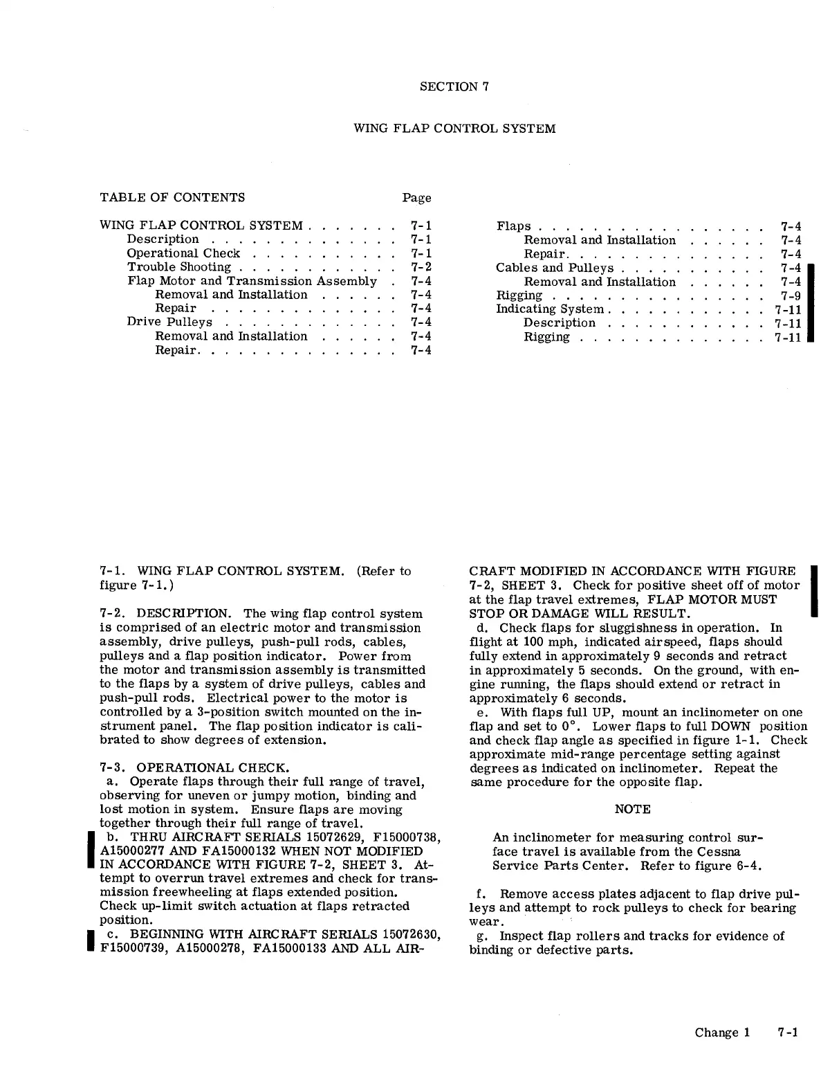
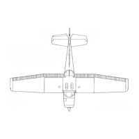
7-2.
DESCIUPTION.
The
wing
flap
control
system
is
comprised
of
an
electric
motor
and
transmission
assembly,
drive
pulleys,
push-pull
rods,
cables,
pulleys
and
a
flap
position
indicator.
Power
from
the
motor
and
transmission
assembly
is
transmitted
to
the
flaps
by
a
system
of
drive
pulleys,
cables
and
push-pull
rods.
Electrical
power
to
the
motor
is
controlled
by
a
3-position
switch
mounted
on
the
in-
strument
panel.
The
flap
position
indicator
is
cali-
brated
to
show
degrees
of
extension.
7-3.
OPERATIONAL CHECK.
a.
Operate
flaps
through
their
full
range
of
travel,
observing
for
uneven
or
jumpy
motion,
binding
and
lost
motion
in
system.
Ensure
flaps
are
moving
together
through
their
full
range
of
travel.
l
b.
THRU AIRCRAFT SEIUALS 15072629, F15000738,
A15000277
AND
FA15000132 WHEN NOT MODIFIED
IN ACCORDANCE WITH FIGURE
7-2,
SHEET
3.
At-
tempt
to
overrun
travel
extremes
and
check
for
trans-
mission
freewheeling
at
flaps
extended
position.
Check
up-limit
switch
actuation
at
flaps
retracted
position.
I
c.
BEGINNING WITH AIRCRAFT SEIUALS 15072630,
F15000739, A15000278, FA15000133
AND
ALL
AIR-
Flaps
..........
.
Removal
and
Installation
Repair
........
.
Cables
and
Pulleys
. . . . .
Removal
and
Installation
Rigging
.....
Indicating
System.
Description
Rigging
...
7-4
7-4
7-4
7-4
I
7-4
7-9
7-11
7-11
7-11
CRAFT
MODIFIED IN ACCORDANCE WITH FIGURE I
7-2,
SHEET
3.
Check
for
positive
sheet
off
of
motor
at
the
flap
travel
extremes,
FLAP
MOTOR MUST
STOP
OR
DAMAGE WILL
RESULT.
d.
Check
flaps
for
sluggishness
in
operation.
In
flight
at
100 mph,
indicated
airspeed,
flaps
should
fully
extend
in
approximately
9
seconds
and
retract
in
approximately
5
seconds.
On
the
ground,
with
en-
gine
running,
the
flaps
should
extend
or
retract
in
approximately
6
seconds.
e.
With
flaps
full
UP,
mount
an
inclinometer
on
one
flap
and
set
to
0°.
Lower
flaps
to
full
DOWN
position
and
check
flap
angle
as
specified
in
figure
1-1.
Check
approximate
mid-range
percentage
setting
against
degrees
as
indicated
on
inclinometer.
Repeat
the
same
procedure
for
the
opposite
flap.
NOTE
An
inclinometer
for
measuring
control
sur-
face
travel
is
available
from
the
Cessna
Service
Parts
Center.
Refer
to
figure
6-4.
f.
Remove
access
plates
adjacent
to
flap
drive
pul-
leys
and
attempt
to
rock
pulleys
to
check
for
bearing
wear.
g.
Inspect
flap
rollers
and
tracks
for
evidence
of
binding
or
defective
parts.
Change
1
7-1