Programmable DC Electronic Load 63600 Series Operation & Programming Manual
VFD Display Symbols
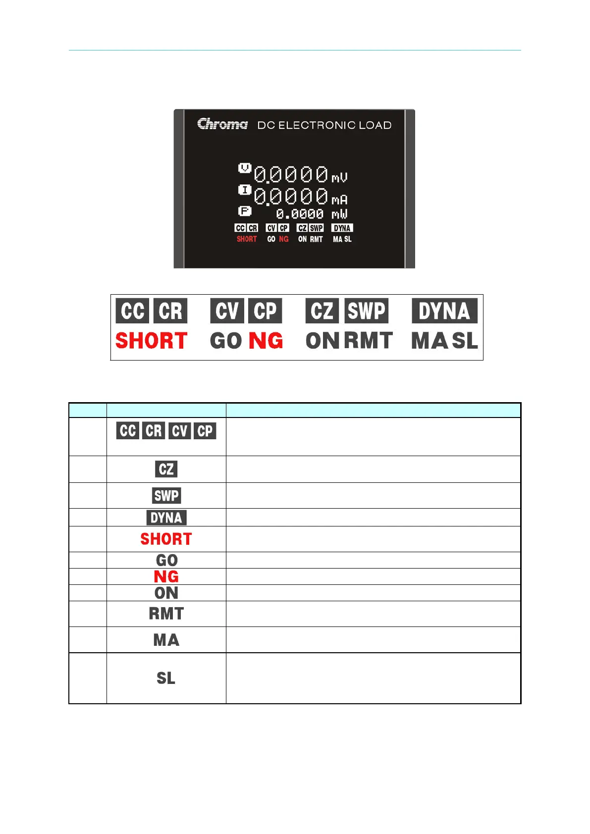
Figure 4-4 VFD Display
Figure 4-5 Symbols of VFD Display
Table 4-2 Definition for VFD Display Symbols on the Module
Indicates acting mode is at one of the followings: constant
current (CC), constant resistance (CR), constant voltage
(CV), or constant power (CP).
Indicates acting mode of impedance load simulation.
Indicates the Electronic Load is in Frequency sweep in
operation.
Indicates the Electronic Load is in Dynamic load operation.
Indicates the Electronic Load is in short circuit simulation for
UUT to test short protection.
This indicates the SPEC inspection for GO (PASS).
This indicates the SPEC inspection for NG (FAIL).
Indicates the load module is in load ON status.
Indicates the remote operation via USB/Ethernet/System or
GPIB bus is enabled.
Indicates the load module is in parallel control mode of
MASTER unit or in Sync Dynamic mode of MASTER unit.
Indicates the load module is in parallel control mode of
SLAVE unit or in Sync Dynamic mode of SLAVE unit. (Slave
module in parallel control mode will show “SLAVE” on the