7�2�3�1�2�- Conguration of a digital input, logic state mode.
When selecting the conguration of digital inputs in logic state mode, you can program the input
logic as positive or negative.
The conguration of a digital input in logic state mode in the expansion modules is the same as
the conguration of the digital inputs in logic state mode integrated in the device, see “5.7.18.3.-
Conguration of digital inputs, logic state mode.”
7�2�3�2�- Relay digital outputs�
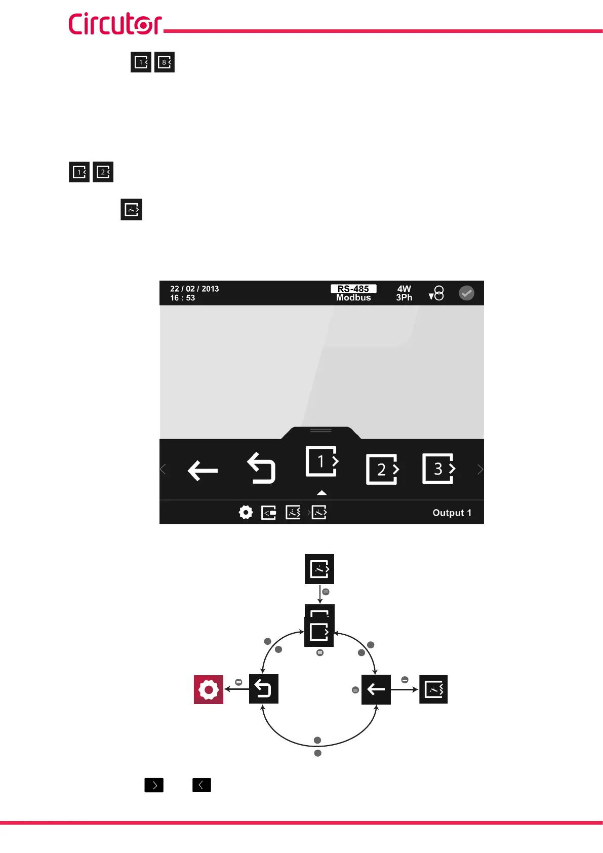
Select the output to congure on the main conguration screen of the relay digital outputs,
Figure 339.
Figure 339: Main conguration screen of relay digital outputs.
>
>
>
<
<
<
varh
8
1
Back
Main
menu
Output 1...8
Figure 340: Setup menu : relay digital outputs
Use the keys and to select the different options.
270
CVM-A1000 - CVM-A1500
Instruction Manual