To conrm the selection, press the key .
After selecting the output to congure, you can congure the following parameters:
The variable code that controls the relay.
The pre-alarm value.
The minimum value below which the relay is activated.
The maximum value above which the relay is activated.
The delay in connecting (ON) and disconnecting (OFF) the relay.
The status of the outputs.
The latch.
The conguration of the relay digital outputs in the expansion modules is the same as the
conguration of the relay digital outputs integrated in the device, see “5.7.16.- RELAY DIGITAL
OUTPUTS.”.
7�2�4�- MODBUS COMMUNICATIONS
The address of the Modbus memory map depends on the position of the expansion module in
the device.
Slot 1 will be the position of the expansion module installed just behind the standard device,
and Slot 2 the next position...
As the maximum number of expansion modules that can be connected to the device is 4, there
will only be 4 slots.
7�2�4�1�- Programming of relay digital outputs
The following functions are implemented for these variables:
Function 0x04: reading registers.
Function 0x10: Writing multiple registers.
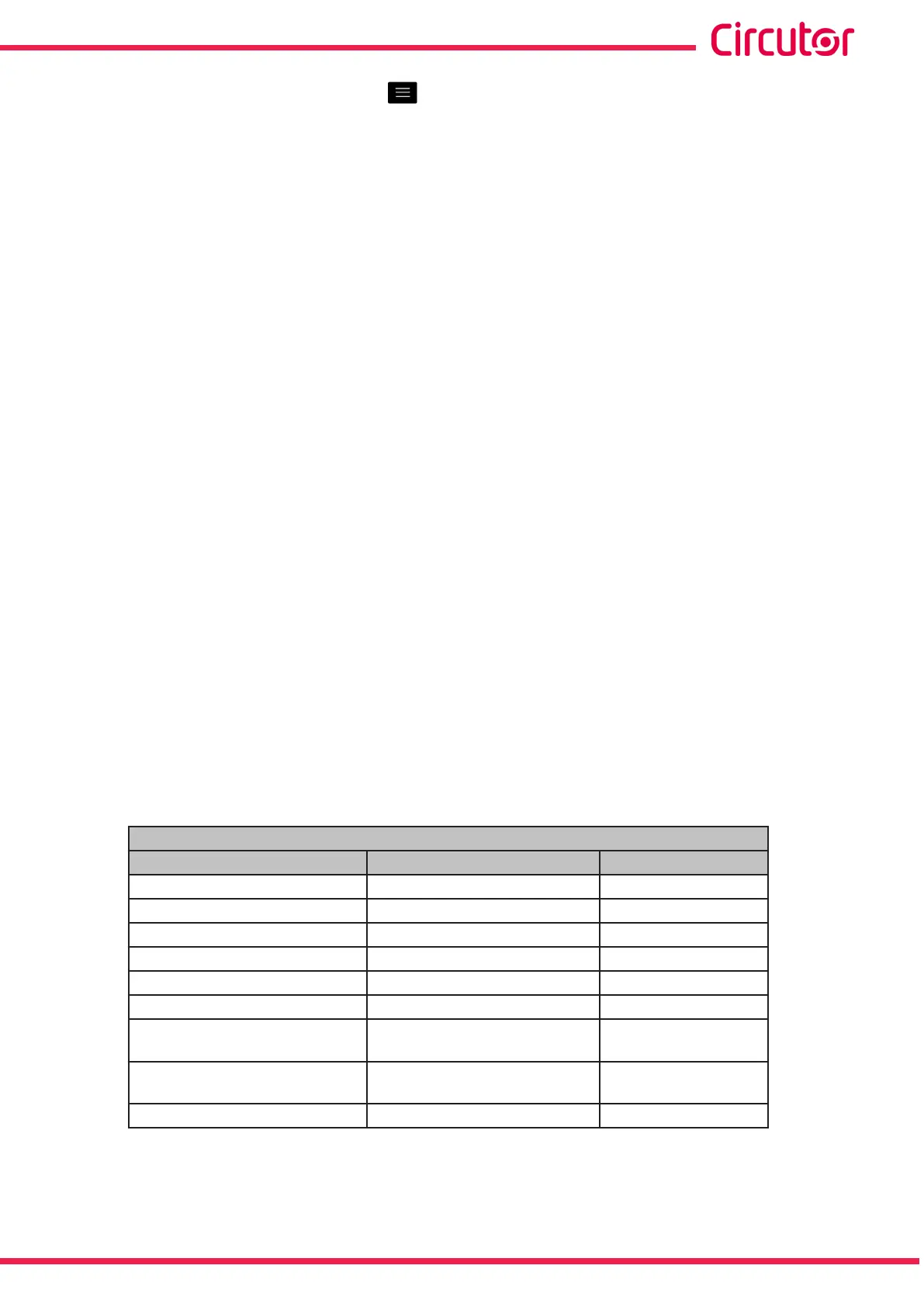
Table 88: Modbus memory map: Relay digital outputs, expansion modules (Table 1)�
Conguration of relay digital outputs
Configuration variable
Valid data window
Default value
Variable code Table 32 and Table 33 0
Pre-alarm value 0 to 100% 0
Minimum value
(76)
Table 61 0
Maximum value
(76)
Table 61 0
Connection delay (ON) 0 to 999 s. 0
Disconnection delay (OFF)
0 to 999 s. 0
Latch
0 : Unlocked
1: Locked
0
Output status
0 : Normally open
1: Normally closed
0
Module no.
0
0
(76)
When programming the maximum and minimum values, the decimals for the variable selected must be includ-
ed.
271
Instruction Manual
CVM-A1000 - CVM-A1500