Procedure
Step 1 Unplug the Ethernet cable from the phone.
Step 2 If installed, remove the footstand from the phone.
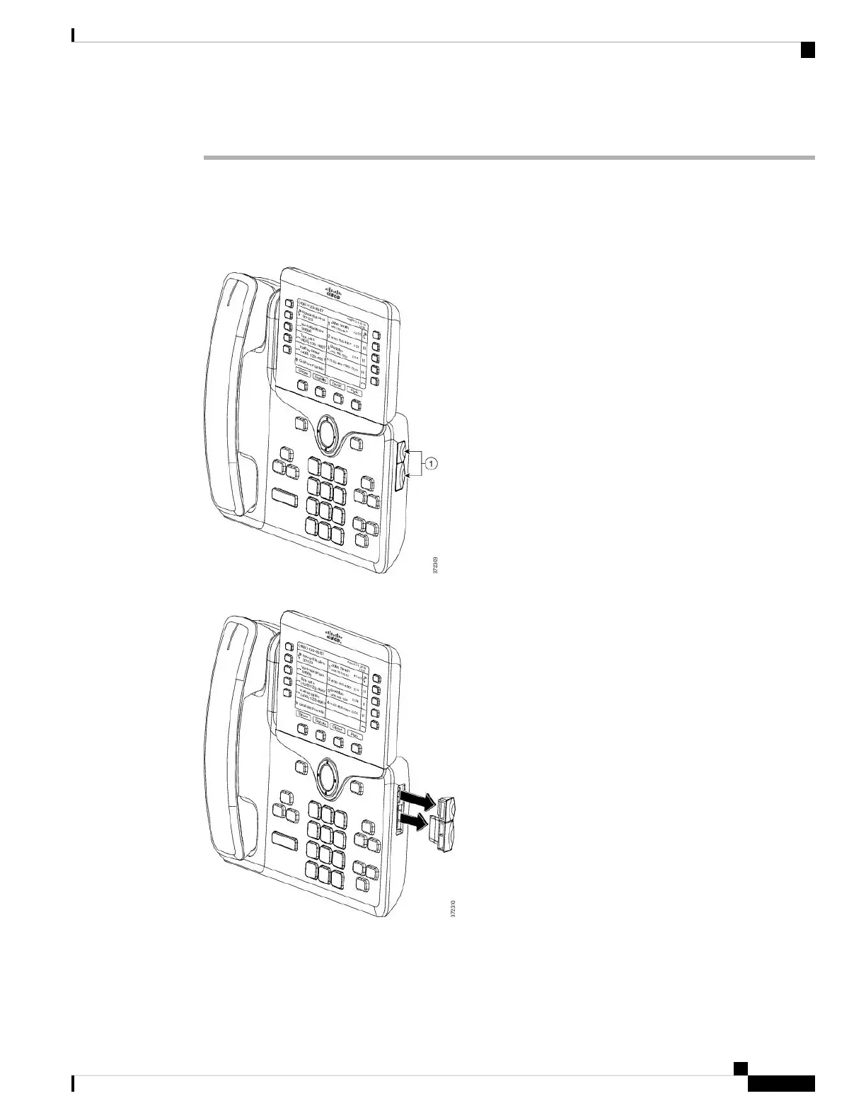
Step 3 Locate the accessory connector covers on the side of the phone.
This diagram shows the location.
Step 4 Remove the two accessory connector covers, as shown in the diagram.
The slots are designed for the spine connector only. Insertion of other objects will cause permanent
damage to the phone.
Caution
Cisco IP Phone 7800 and 8800 Series Accessories Guide for Cisco Unified Communications Manager
57
Key Expansion Modules
Connect a Key Expansion Module to a Cisco IP Phone
 Loading...