20-4
Catalyst 2950 and Catalyst 2955 Switch Software Configuration Guide
78-11380-12
Chapter 20 Configuring IGMP Snooping and MVR
Understanding IGMP Snooping
Router A sends a general query to the switch, which forwards the query to ports 2 through 5, all members
of the same VLAN. Host 1 wants to join multicast group 224.1.2.3 and multicasts an IGMP membership
report (IGMP join message) to the group with the equivalent MAC destination address of
0x0100.5E01.0203. When the CPU receives the IGMP report multicast by Host 1, the CPU uses the
information in the IGMP report to set up a forwarding-table entry, as shown in Table 20-1, that includes
the port numbers of Host 1, the router, and the switch internal CPU.
Note that the switch hardware can distinguish IGMP information packets from other packets for the
multicast group.
• The first entry in the table tells the switching engine to send IGMP packets to only the switch CPU.
This prevents the CPU from becoming overloaded with multicast frames.
• The second entry tells the switching engine to send frames addressed to the 0x0100.5E01.0203
multicast MAC address that are not IGMP packets (!IGMP) to the router and to the host that has
joined the group.
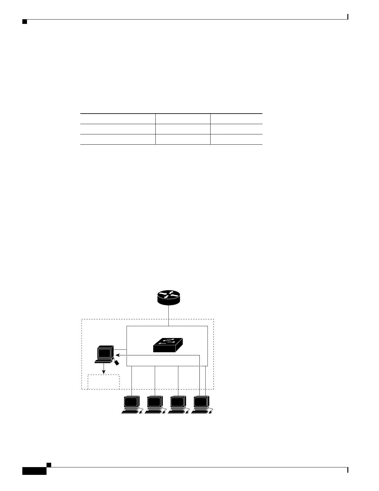
If another host (for example, Host 4) sends an unsolicited IGMP join message for the same group
(Figure 20-2), the CPU receives that message and adds the port number of Host 4 to the forwarding table
as shown in Table 20-2. Note that because the forwarding table directs IGMP messages to only the CPU,
the message is not flooded to other ports on the switch. Any known multicast traffic is forwarded to the
group and not to the CPU. Any unknown multicast traffic is flooded to the VLAN and sent to the CPU
until it becomes known.
Figure 20-2 Second Host Joining a Multicast Group
Table 20-1 IGMP Snooping Forwarding Table
Destination Address Type of Packet Ports
0100.5exx.xxxx IGMP 0
0100.5e01.0203 !IGMP 1, 2
Forwarding
table
CPU
Host 1 Host 2 Host 3 Host 4
Router A
PFC
VLAN
1
0
234 5
45751