CHAPTER
7-1
Catalyst 2960 and 2960-S Switches Software Configuration Guide, Release 15.0(1)SE
OL-26520-01
7
Managing Switch Stacks
This chapter provides the concepts and procedures to manage Catalyst 2960-S stacks, also referred to as
Cisco FlexStacks. See the command reference for command syntax and usage information.
Note Stacking is supported only on Catalyst 2960-S switches running the LAN base image.
• Understanding Stacks, page 7-1
• Configuring the Switch Stack, page 7-17
• Accessing the CLI of a Specific Member, page 7-22
• Displaying Stack Information, page 7-23
• Troubleshooting Stacks, page 7-23
Note A stack can have only Catalyst 2960-S member switches.
For other switch stack-related information, such as cabling the switches through their stack ports and
using the LEDs for switch stack status, see the hardware installation guide.
Understanding Stacks
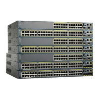
A switch stack is a set of up to four Catalyst 2960-S switches connected through their stack ports. One
of the switches controls the operation of the stack and is called the stack master. The stack master and
the other switches in the stack are stack members. Layer 2 protocol presents the entire switch stack as a
single entity to the network.
Note A switch stack is different from a switch cluster. A switch cluster is a set of switches connected through
their LAN ports, such as the 10/100/1000 ports. For more information about how switch stacks differ
from switch clusters, see the “Planning and Creating Clusters” chapter in the Getting Started with Cisco
Network Assistant on Cisco.com.
The master is the single point of stack-wide management. From the master, you configure:
• System-level (global) features that apply to all members
• Interface-level features for each member

 Loading...


