17-15
Catalyst 2960 and 2960-S Switches Software Configuration Guide, Release 15.0(1)SE
OL-26520-01
Chapter 17 Configuring MSTP
Configuring MSTP Features
For information about the supported number of spanning-tree instances, see the “Supported
Spanning-Tree Instances” section on page 16-10.
MSTP Configuration Guidelines
Note Stacking is supported only on Catalyst 2960-S switches running the LAN base image.
These are the configuration guidelines for MSTP:
• When you enable MST by using the spanning-tree mode mst global configuration command, RSTP
is automatically enabled.
• For two or more stacked switches to be in the same MST region, they must have the same
VLAN-to-instance map, the same configuration revision number, and the same name.
• The switch stack supports up to 65 MST instances. The number of VLANs that can be mapped to a
particular MST instance is unlimited.
• PVST+, rapid PVST+, and MSTP are supported, but only one version can be active at any time. (For
example, all VLANs run PVST+, all VLANs run rapid PVST+, or all VLANs run MSTP.) For more
information, see the “Spanning-Tree Interoperability and Backward Compatibility” section on
page 16-11. For information on the recommended trunk port configuration, see the “Interaction with
Other Features” section on page 13-16.
• All stack members run the same version of spanning tree (all PVST+, rapid PVST+, or MSTP). For
more information, see the “Spanning-Tree Interoperability and Backward Compatibility” section on
page 16-11.
• VTP propagation of the MST configuration is not supported. However, you can manually configure
the MST configuration (region name, revision number, and VLAN-to-instance mapping) on each
switch within the MST region by using the command-line interface (CLI) or through the SNMP
support.
• For load balancing across redundant paths in the network to work, all VLAN-to-instance mapping
assignments must match; otherwise, all traffic flows on a single link. You can achieve load balancing
across a switch stack by manually configuring the path cost.
• All MST boundary ports must be forwarding for load balancing between a PVST+ and an MST
cloud or between a rapid-PVST+ and an MST cloud. For this to occur, the IST master of the MST
cloud should also be the root of the CST. If the MST cloud consists of multiple MST regions, one
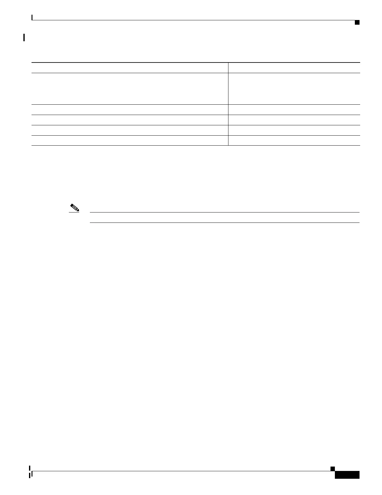
Spanning-tree port cost (configurable on a per-CIST port basis) 1000 Mbps: 4.
100 Mbps: 19.
10 Mbps: 100.
Hello time 2 seconds.
Forward-delay time 15 seconds.
Maximum-aging time 20 seconds.
Maximum hop count 20 hops.
Table 17-4 Default MSTP Configuration (continued)
Feature Default Setting