6-8
Catalyst 2960 and 2960-S Switches Software Configuration Guide, Release 15.0(1)SE
OL-26520-01
Chapter 6 Clustering Switches
Planning a Switch Cluster
Note If the switch cluster has a Catalyst 3750 or 2960-S switch or has a switch stack, that switch or switch
stack must be the cluster command switch.
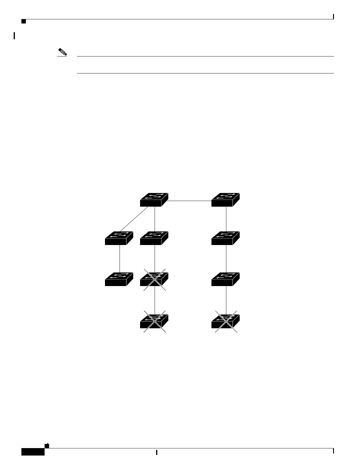
The cluster command switch and standby command switch in Figure 6-4 (assuming they are
Catalyst 2960, Catalyst 2970, Catalyst 2975, Catalyst 3550, Catalyst 3560, or Catalyst 3750 cluster
command switches) have ports assigned to VLANs 9, 16, and 62. The management VLAN on the cluster
command switch is VLAN 9. Each cluster command switch discovers the switches in the different
management VLANs except these:
• Switches 7 and 10 (switches in management VLAN 4) because they are not connected through a
common VLAN (meaning VLANs 62 and 9) with the cluster command switch
• Switch 9 because automatic discovery does not extend beyond a noncandidate device, which is
switch 7
Figure 6-4 Discovery Through Different Management VLANs with a Layer 3 Cluster Command
Switch
Discovery of Newly Installed Switches
To join a cluster, the new, out-of-the-box switch must be connected to the cluster through one of its
access ports. An access port carries the traffic of and belongs to only one VLAN. By default, the new
switch and its access ports are assigned to VLAN 1.
When the new switch joins a cluster, its default VLAN changes to the VLAN of the immediately
upstream neighbor. The new switch also configures its access port to belong to the VLAN of the
immediately upstream neighbor.
101323
VLAN 62
VLAN trunk 4, 62
VLAN 62
VLAN 16
VLAN 9
VLAN 16
VLAN 9
Standby command
device
Command
device
VLAN 9
Device 7
(management
VLAN 4)
Device 9
(management
VLAN 62)
VLAN 4
Device 3
(management
VLAN 16)
Device 4
(management
VLAN 16)
Device 10
(management
VLAN 4)
Device 8
(management
VLAN 9)
Device 6
(management
VLAN 9)
Device 5
(management
VLAN 62)