EasyManua.ls Logo

Cisco CATALYST 2960 User Manual

Cisco CATALYST 2960
980 pages
To Next Page IconTo Next Page
To Previous Page IconTo Previous Page
Page #689 background imageLoading...
Page #689 background image
30-3
Catalyst 2960 and 2960-S Switches Software Configuration Guide, Release 15.0(1)SE
OL-26520-01
Chapter 30 Configuring SNMP
Understanding SNMP
SNMPv2C includes a bulk retrieval mechanism and more detailed error message reporting to
management stations. The bulk retrieval mechanism retrieves tables and large quantities of information,
minimizing the number of round-trips required. The SNMPv2C improved error-handling includes
expanded error codes that distinguish different kinds of error conditions; these conditions are reported
through a single error code in SNMPv1. Error return codes in SNMPv2C report the error type.
SNMPv3 provides for both security models and security levels. A security model is an authentication
strategy set up for a user and the group within which the user resides. A security level is the permitted
level of security within a security model. A combination of the security level and the security model
determine which security mechanism is used when handling an SNMP packet. Available security models
are SNMPv1, SNMPv2C, and SNMPv3.
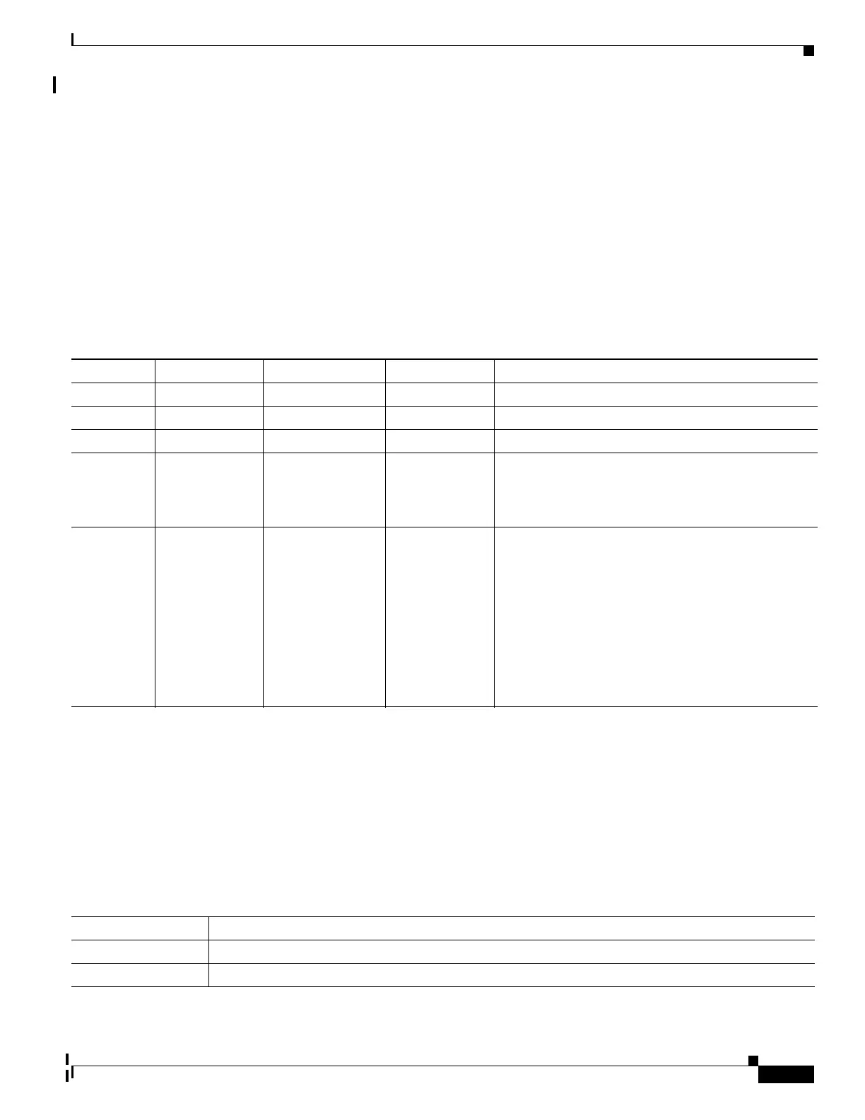
Table 30-1 identifies the characteristics of the different combinations of security models and levels.
You must configure the SNMP agent to use the SNMP version supported by the management station.
Because an agent can communicate with multiple managers, you can configure the software to support
communications using SNMPv1, SNMPv2C, or SNMPv3.
SNMP Manager Functions
The SNMP manager uses information in the MIB to perform the operations described in Table 30-2.
Table 30-1 SNMP Security Models and Levels
Model Level Authentication Encryption Result
SNMPv1 noAuthNoPriv Community string No Uses a community string match for authentication.
SNMPv2C noAuthNoPriv Community string No Uses a community string match for authentication.
SNMPv3 noAuthNoPriv Username No Uses a username match for authentication.
SNMPv3 authNoPriv Message Digest 5
(MD5) or Secure
Hash Algorithm
(SHA)
No Provides authentication based on the HMAC-MD5 or
HMAC-SHA algorithms.
SNMPv3 authPriv
(requires the
cryptographic
software image)
MD5 or SHA Data Encryption
Standard (DES)
or Advanced
Encryption
Standard (AES)
Provides authentication based on the HMAC-MD5 or
HMAC-SHA algorithms. Allows specifying the
User-based Security Model (USM) with these
encryption algorithms:
DES 56-bit encryption in addition to
authentication based on the CBC-DES (DES-56)
standard.
3DES 168-bit encryption
AES 128-bit, 192-bit, or 256-bit encryption
Table 30-2 SNMP Operations
Operation Description
get-request Retrieves a value from a specific variable.
get-next-request Retrieves a value from a variable within a table.
1

Table of Contents

Other manuals for Cisco CATALYST 2960

Questions and Answers:

Cisco CATALYST 2960 Specifications

General IconGeneral
ManageableYes
StackingNo
ModelCatalyst 2960 Series Switches
Power over Ethernet (PoE)Available on some models (IEEE 802.3af)
VLANs255 active VLANs
FeaturesQoS
Operating Temperature32 to 113°F (0 to 45°C)
Relative Humidity10% to 85% non-condensing
Power ConsumptionVaries by model (30W to 400W)

Summary

Preface

Purpose

Provides information on configuring Cisco IOS software features on switches.

Chapter 1 Overview

Features

Details the capabilities of LAN base and LAN Lite images on Catalyst switches.

Ease-of-Deployment and Ease-of-Use Features

User-defined and Cisco-default Smartports macros for creating custom switch configurations for simplified deployment across the network.

Details Cisco-default and user-defined macros for dynamic port configuration based on detected device type.

Cisco Network Assistant (hereafter referred to as Network Assistant) for

Covers Cisco Network Assistant for managing multiple switches and simplifying tasks.

Performance Features

Autosensing of port speed and autonegotiation of duplex mode on all switch ports for optimizing bandwidth.

Details autosensing of port speed and autonegotiation of duplex mode for bandwidth optimization.

Per-port storm control for preventing broadcast, multicast, and unicast storms.

Details per-port storm control for preventing broadcast, multicast, and unicast storms.

Management Options

Manageability Features

CNS embedded agents for automating switch management, configuration storage, and delivery

Covers CNS embedded agents for automating switch management, configuration storage, and delivery.

DHCP for automating configuration of switch information (such as IP address, default gateway, hostname, and Domain Name System [DNS] and TFTP server names)

Details DHCP for automating switch information configuration (IP address, gateway, hostname, DNS, TFTP).

Availability and Redundancy Features

Cross-stack EtherChannel for providing redundant links across the switch stack

Explains cross-stack EtherChannel for redundant links across switch stacks.

VLAN Features

Support for up to 255 VLANs for assigning users to VLANs associated with appropriate network resources, traffic patterns, and bandwidth

Explains support for up to 255 VLANs for assigning users based on resources, traffic, and bandwidth.

Security Features

IEEE 802.1x Authentication with ACLs and the RADIUS Filter-Id Attribute

Explains IEEE 802.1x Authentication with ACLs and RADIUS Filter-Id Attribute.

Port security option for limiting and identifying MAC addresses of the stations allowed to access the port

Covers port security option for limiting and identifying MAC addresses of allowed stations.

QoS and CoS Features

Automatic QoS (auto-QoS) to simplify the deployment of existing QoS features by classifying traffic and configuring egress queues

Details auto-QoS for simplifying QoS deployment via traffic classification and egress queue configuration.

Power over Ethernet Features

Universal Power over Ethernet Features

Provides the ability to source up to 60 W of power over standard Ethernet cabling infrastructure.

Details ability to source up to 60W power over standard Ethernet cabling.

Monitoring Features

Switched Port Analyzer (SPAN) and Remote SPAN (RSPAN) for traffic monitoring on any port or VLAN

Covers SPAN and RSPAN for traffic monitoring on any port or VLAN.

Four groups (history, statistics, alarms, and events) of embedded RMON agents for network monitoring and traffic analysis

Explains embedded RMON agents for network monitoring and traffic analysis (history, stats, alarms, events).

Default Settings After Initial Switch Configuration

VLANs

DHCP snooping is disabled. The DHCP snooping information option is enabled. For more information, see Chapter 20, “Configuring DHCP and IP Source Guard Features.”

Network Configuration Examples

“Design Concepts for Using the Switch” section on page 1-19

Discusses design concepts for using the switch.

“Long-Distance, High-Bandwidth Transport Configuration” section on page 1-25

Details configuration for long-distance, high-bandwidth transport.

Design Concepts for Using the Switch

Table 1-2 Providing Network Services (continued)

Suggested Design Methods

Provides design methods for IP telephony and network speed requirements.

You can use the switches and switch stacks to create the following:

Cost-effective Gigabit-to-the-desktop for high-performance workgroups (Figure 1-2)—For high-speed access to network resources, you can use the Catalyst 2960 switch in the access layer to provide Gigabit Ethernet to the desktop. To prevent congestion, use QoS DSCP marking priorities on these switches. For high-speed IP forwarding at the distribution layer, connect the switches in the access layer to a Gigabit multilayer switch with routing capability, such as a Catalyst 3750 switch, or to a router.

Server aggregation (Figure 1-3)—You can use the switches and switch stacks to interconnect groups of servers, centralizing physical security and administration of your network. For high-speed IP forwarding at the distribution layer, connect the switches in the access layer to multilayer switches with routing capability. The Gigabit interconnections minimize latency in the data flow.

Small to Medium-Sized Network Using Catalyst 2960, 2960-S and 2960-C Switches

Long-Distance, High-Bandwidth Transport Configuration

Where to Go Next

Before configuring the switch, review these sections for startup information:

Suggests reviewing sections for startup information before configuring the switch.

Chapter 2, “Using the Command-Line Interface”

References Chapter 2 for information on using the command-line interface.

Chapter 3, “Assigning the Switch IP Address and Default Gateway”

References Chapter 3 for assigning switch IP address and default gateway.

CHAPTER 2

Using the Command-Line Interface

Describes the Cisco IOS command-line interface (CLI) and its usage for switch configuration.

Understanding Command Modes

Understanding the Help System

Understanding Abbreviated Commands

Understanding no and default Forms of Commands

Understanding CLI Error Messages

Table 2-3 lists some error messages that you might encounter while using the CLI to configure your switch.

Lists common CLI error messages encountered during switch configuration.

Using Configuration Logging

Using Command History

Recalling Commands

Disabling the Command History Feature

The command history feature is automatically enabled. You can disable it for the current terminal session or for the command line. These procedures are optional.

Explains that command history is enabled by default and can be disabled for terminal session or command line.

Using Editing Features

Enabling and Disabling Editing Features

Editing Commands through Keystrokes

Chapter 2 Using the Command-Line Interface

Searching and Filtering Output of show and more Commands

Explains how to search and filter output of show and more commands.

Accessing the CLI

Describes accessing the CLI via console, Telnet, or browser for managing switch stacks.

Accessing the CLI

Accessing the CLI through a Console Connection or through Telnet

CHAPTER 3

Assigning the Switch IP Address and Default Gateway

Describes configuring initial switch settings like IP address and default gateway.

Assigning Switch Information

You can assign IP information through the switch setup program, through a DHCP server, or manually.

Explains assigning IP information via setup program, DHCP server, or manually.

Understanding DHCP-Based Autoconfiguration

DHCP Client Request Process

The client, Switch A, broadcasts a DHCPDISCOVER message to locate a DHCP server. The DHCP server offers configuration parameters (such as an IP address, subnet mask, gateway IP address, DNS IP address, a lease for the IP address, and so forth) to the client in a DHCPOFFER unicast message.

The DHCP server confirms that the IP address has been allocated to the client by returning a DHCPACK unicast message to the client. With this message, the client and server are bound, and the client uses configuration information received from the server. The amount of information the switch receives depends on how you configure the DHCP server. For more information, see the “Configuring the TFTP Server” section on page 3-7.

Understanding DHCP-based Autoconfiguration and Image Update

DHCP Autoconfiguration

DHCP Auto-Image Update

Configuring DHCP-Based Autoconfiguration

DHCP Server Configuration Guidelines, page 3-6

Provides DHCP server configuration guidelines.

DHCP Server Configuration Guidelines

Configuring the TFTP Server

Configuring the DNS

Configuring the Relay Device

Example Configuration

TFTP Server Configuration (on UNIX)

Configuring DHCP Autoconfiguration (Only Configuration File)

Configuring the Client

Manually Assigning IP Information

Beginning in privileged EXEC mode, follow these steps to manually assign IP information to multiple switched virtual interfaces (SVIs):

Details steps to manually assign IP information to multiple switched virtual interfaces (SVIs).

Checking and Saving the Running Configuration

You can check the configuration settings that you entered or changes that you made by entering this privileged EXEC command:

Describes checking entered configuration settings or changes via privileged EXEC command.

Configuring the NVRAM Buffer Size

Modifying the Startup Configuration

Default Boot Configuration

Automatically Downloading a Configuration File

Specifying the Filename to Read and Write the System Configuration

Booting Manually

Booting a Specific Software Image

Controlling Environment Variables

Scheduling a Reload of the Software Image

Configuring a Scheduled Reload

To configure your switch to reload the software image at a later time, use one of these commands in privileged EXEC mode:

Details commands to configure software image reload at a later time in privileged EXEC mode.

Displaying Scheduled Reload Information

CHAPTER 4

Configuring Cisco IOS Configuration Engine

Describes configuring Cisco IOS Configuration Engine feature on Catalyst switches.

Understanding Cisco Configuration Engine Software

Configuration Service

Event Service

NameSpace Mapper

What You Should Know About the CNS IDs and Device Hostnames

ConfigID

DeviceID

Hostname and DeviceID

Configuring Cisco IOS Agents

Enabling Automated CNS Configuration

Table 4-1 Prerequisites for Enabling Automatic Configuration

Required Configuration

Specifies the required configuration for automatic setup.

Enabling the CNS Event Agent

Incremental (Partial) Configuration

Synchronized Configuration

Enabling an Initial Configuration

Beginning in privileged EXEC mode, follow these steps to enable the CNS configuration agent and initiate an initial configuration on the switch:

Details steps to enable CNS configuration agent and initiate initial configuration in privileged EXEC mode.

CHAPTER 5

Administering the Switch

Describes one-time operations for administering Catalyst 2960, 2960-S, or 2960-C switches.

Identifying the Switch Image

The Catalyst 2960 and 2960-S switches run one of these images:

States Catalyst 2960/2960-S switches run LAN base or LAN Lite images.

Managing the System Time and Date

Understanding the System Clock

Understanding Network Time Protocol

NTP Version 4

Configuring Time and Date Manually

Setting the System Clock

Configuring a System Name and Prompt

Understanding the DNS

Default System Name and Prompt Configuration

Configuring a System Name

Beginning in privileged EXEC mode, follow these steps to manually configure a system name:

Details steps to manually configure a system name in privileged EXEC mode.

CHAPTER 6

Clustering Switches

Provides concepts and procedures for creating and managing Catalyst 2960, 2960-S, or 2960-C switch clusters.

Understanding Switch Clusters

Cluster Command Switch Characteristics

A cluster command switch must meet these requirements:

Lists requirements for a cluster command switch.

Standby Cluster Command Switch Characteristics

A standby cluster command switch must meet these requirements:

Lists requirements for a standby cluster command switch.

Candidate Switch and Cluster Member Switch Characteristics

Planning a Switch Cluster

Automatic Discovery of Cluster Candidates and Members

Discovery Through CDP Hops

Discovery Through Non-CDP-Capable and Noncluster-Capable Devices

Discovery Through Different VLANs

Discovery Through Different Management VLANs

Discovery of Newly Installed Switches

HSRP and Standby Cluster Command Switches

Virtual IP Addresses

Other Considerations for Cluster Standby Groups

CHAPTER 7

Managing Switch Stacks

Provides concepts and procedures for managing Catalyst 2960-S stacks (Cisco FlexStacks).

Understanding Stacks

Stack Membership

Master Election

The stack master is elected based on one of these factors in the order listed:

Explains stack master election based on factors in listed order.

Stack MAC Address

Member Numbers

Stack Offline Configuration

Effects of Adding a Provisioned Switch to a Stack

Effects of Removing a Provisioned Switch from a Stack

Stack Software Compatibility Recommendations

All stack members must run the same Cisco IOS software version to ensure compatibility in the stack protocol version among the members.

States all stack members must run the same Cisco IOS software version for stack protocol compatibility.

Stack Protocol Version Compatibility

Major Version Number Incompatibility Among Switches

Switches with different Cisco IOS software versions likely have different stack protocol versions. Switches with different major version numbers are incompatible and cannot exist in the same stack.

States switches with different IOS versions likely have different stack protocol versions; major version differences cause incompatibility.

Minor Version Number Incompatibility Among Switches

Understanding Auto-Upgrade and Auto-Advise

Stack Configuration Files

Stack Management Connectivity

Stack Through an IP Address

Stack Through an SSH Session

Stack Through Console Ports

Specific Members

Configuring the Switch Stack

Default Switch Stack Configuration, page 7-17

Provides default switch stack configuration.

Enabling Persistent MAC Address

Related product manuals