Chapter 3 Disassembly and Maintenance
3-6 Disassembly, Reassembly and Lubrication
CL-S400DT 3-12
J4
J5
J3
J13
J8
J7
SA FFC LCD
SA Main PCB
SA Head Cable
Tape
White (3P)
White (2P)
Blue (2P)
White (4P)
Blue tape
SA2 Base Frame
SA Mechanism Frame
BH (N), M3x6 (NI)
Hook
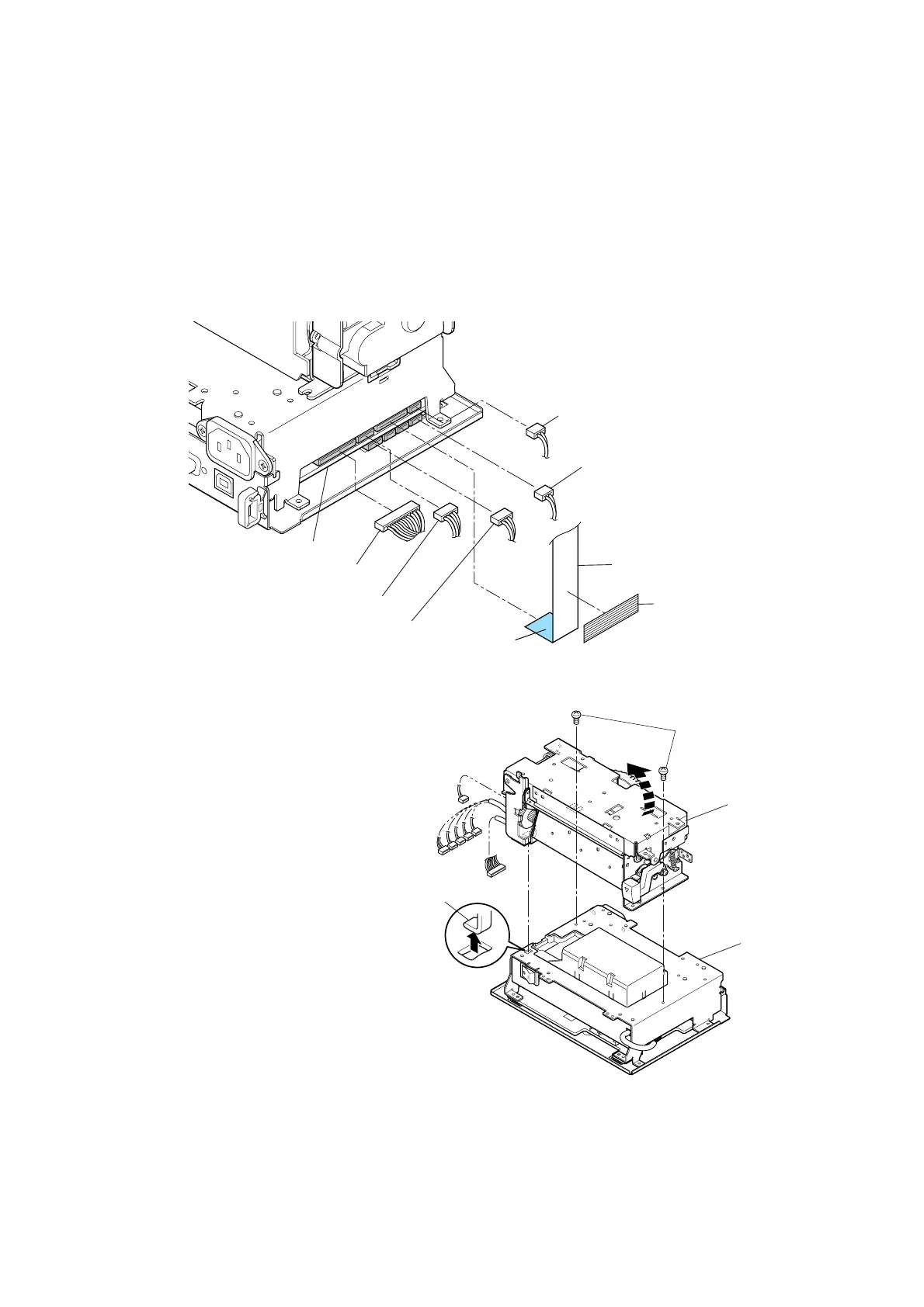
3-6-4. Disconnecting “SA Mechanism Frame” from “SA2 Base Frame”
1. Remove the “SA Cover”. Refer to “3-6-2 SA Cover and SA LCD PCB”.
2. Remove the “Case” from the main body. Refer to “
3-6-3 Case”.
3. Peel off the tape from the frame to se the “SA FFC LCD” free.
4. Disconnect the following 5 cable connectors and “SA FFC LCD”.
In ( ), number of pins and connector color are shown.
- J3 (SA FFC LCD): To SA LCD PCB - J8 (2P: White): To SA Adjust Sensor U
- J4 (16P): To SA2 Head - J5 (4P: White): To Unit, Motor
- J7 (3P: White): To SA Adjust Sensor L - J13 (2P: Blue): To SA Head Up SW
5. Remove 2 screws (BH (N), M3x6 (NI)) and
detach the “SA Mechanism Frame” from the
“SA2 Base Frame” by turning it in the
direction of the arrow.
* When it is turned in the direction of the
arrow, its hook comes off the “SA2 Base
Frame”.
Notes on reassembling:
• Insert the “SA FFC LCD” with the blue tape facing up.
• Match the color of the connectors on the PCB side and the cable side.
e.g. Connect the blue cable connector to the blue connector of the PCB.
* Even if a connector is mistakenly connected, the circuitry is not damaged.

 Loading...


