Chapter 3 Disassembly and Maintenance
3-6 Disassembly, Reassembly and Lubrication
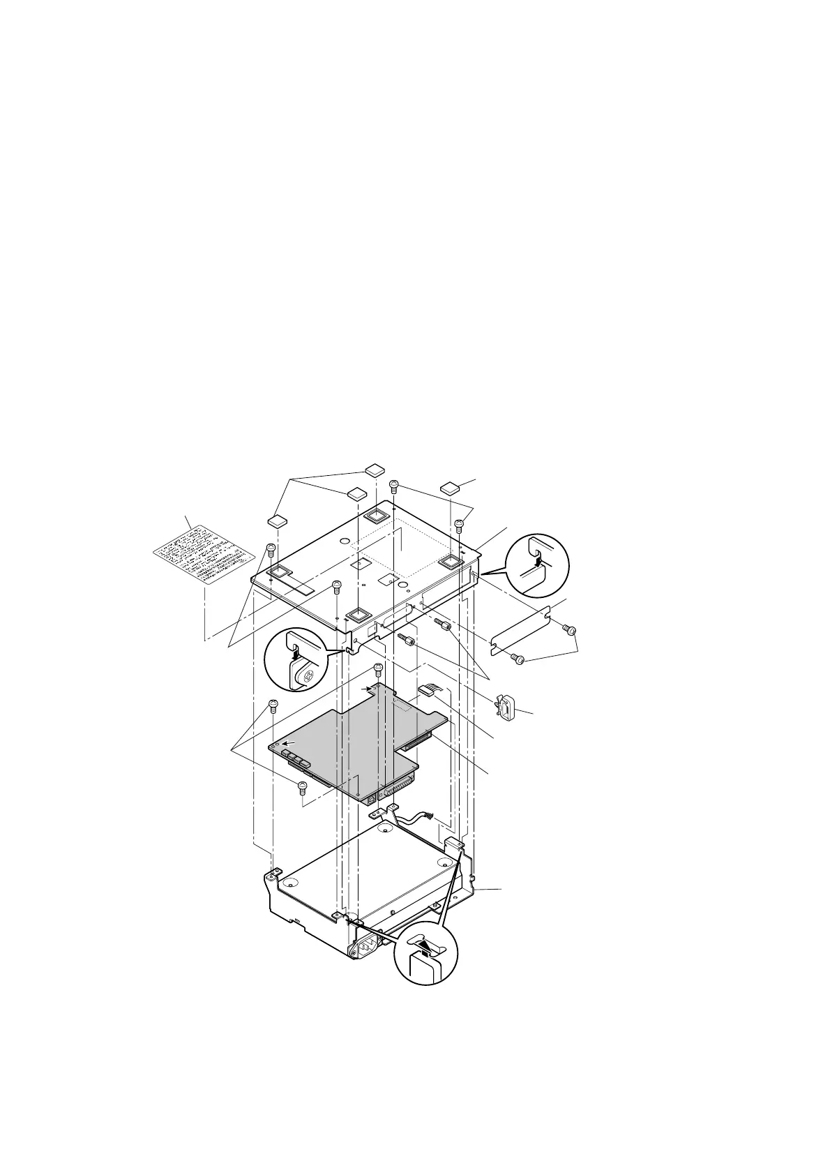
3-13 CL-S400DT
Frame Bottom
SA Main PCB
Lock Screw (Inch)
Leg
Leg
BH (N), M3x6 (NI)
BH (N), M3x6 (NI)
BH (N), M3x6 (NI)
BH (N), M3x6 (NI)
LWS-1S (Cable, Clamp)
Plate, I/F Cover
SA Power Cable
Label, FCC ECES VCCI-A
A
A
"SA Power Supply" block
3-6-5. SA Main PCB
* The “SA Main PCB” can be detached separately without disassembling the printer.
For details, refer to “
3-5-3 SA Main PCB”.
1. Remove the “SA Cover”. Refer to “
3-6-2 SA Cover and SA LCD PCB”.
2. Remove the “Case” from the main body. Refer to “
3-6-3 Case”.
3. Disconnect the “SA Mechanism Frame” from the “SA2 Base Frame”. Refer to “
3-6-4
Disconnecting “SA Mechanism Frame” from “SA2 Base Frame””.
4. Turn over the “SA2 Base Frame”.
5. Remove 2 “Lock Screw (Inch)”.
6. Remove 4 screws (BH (N), M3x6 (NI)) and detach the “Frame Bottom”.
7. Disconnect the connector of the “SA Power Cable” from the “SA Main PCB”.
8. Remove 3 screws (BH (N), M3x6 (NI)) and detach the “SA Main PCB” from the “SA Power
Supply” block.
9. Remove 2 screws (BH (N), M3x6 (NI)) and detach the “Plate, I/F Cover”.
10. Remove the “LWS-1S (Cable, Clamp)”, 4 “Leg” and “Label, FCC ECES VCCI-A” (for CSA only)
from the “Frame Bottom”.
Notes on reassembling:
• When assembling, align the positioning holes “A” (2 places) of the “SA Main PCB” with 2 bosses
of the main body. (Refer to the above figure.)
• Correctly connect the “Frame Bottom” to the main body referring to the enlarged views.

 Loading...


