Chapter 2 Operating Principles
2-2. Operation of Control Parts
CL-S400DT 2-12
2-2. Operation of Control Parts
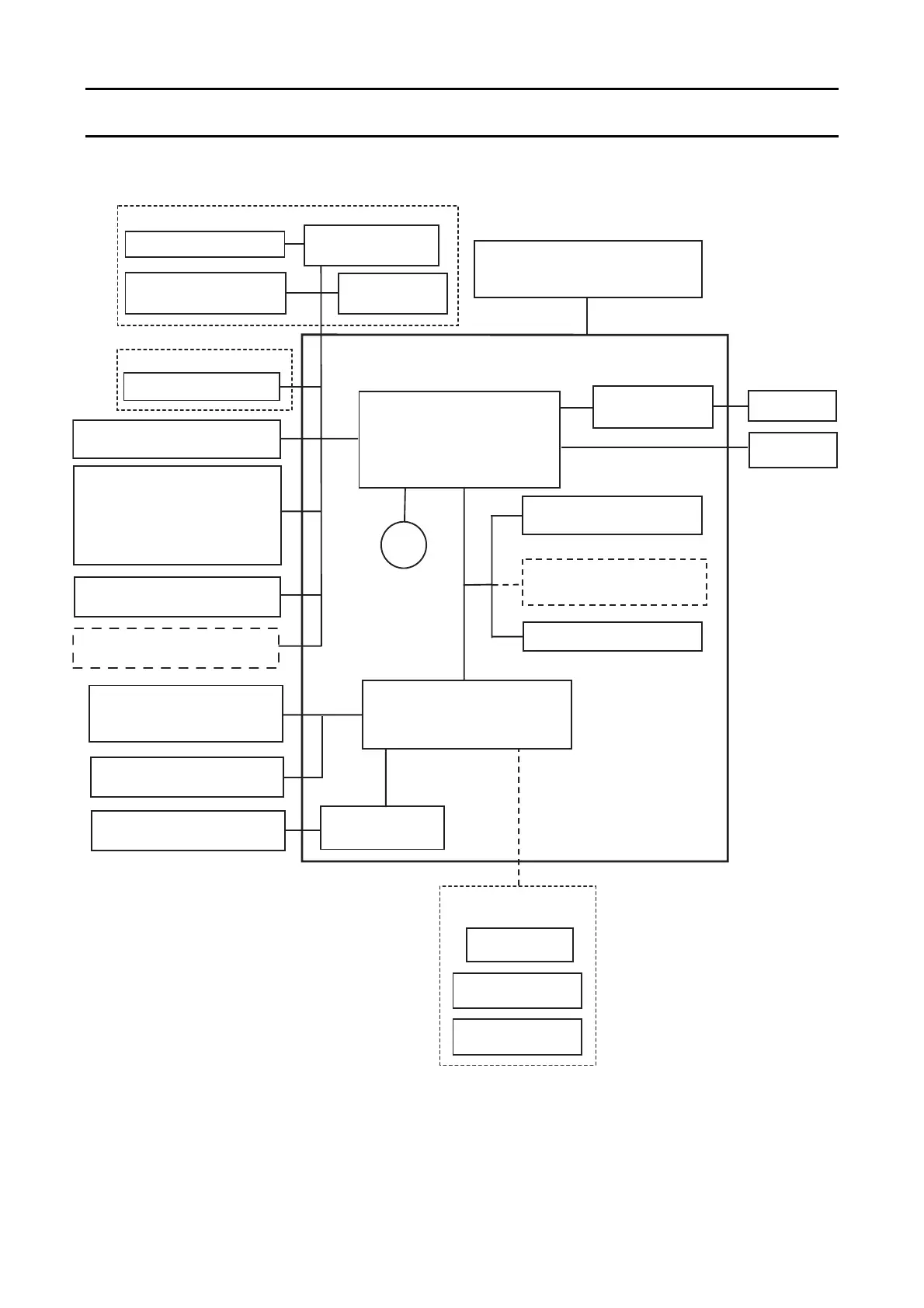
2-2-1. Configuration of Printer
The following shows major configuration blocks.
CPU
UPD703111BGJ-13-UEV-A
128MHz
Head Up Sensor
[SA Head Up SW]
AC Inlet & Power Switch
Flilter & Power Supply
[SA Power Supply]
S-DRAM (128Mbits)
Control / C.G.
F-ROM (64Mbits)
Unit, Motor
Stepping Motor
Driver
FPGA
EP2C5F256C8N
RS232C
IEEE1284
USB 2.0
(Full speed)
SA Main PCB
Peel Sensor
(Option) Peeler Unit
Thermal Head Temp. Sensor
[SA2 Head]
RS232C
Driver/Receiver
Cutter Position Sensor
Cutter Motor Driver
(Option) Auto Cutter Unit
Cutter Motor
Ethernet I/F
(Multi-function type)
(Option) I/F Board
Operation Panel
(LCD/SWx4/LEDx2)
[SA LCD PCB]
SA2 Head
C.G (For CHN)
F-ROM (64Mbits)
Buzzer
Ethernet I/F
(Standard type)
Cutter Motor
Temp. Sensor
Adjustable Sensor:
Motor Temp. Sensor
[SA Motor]
Transparent Sensor
[SA Adjust Sensor U]
Reflective Sensor
[SA Adjust Sensor L]

 Loading...


