Chapter 3 Disassembly and Maintenance
3-6 Disassembly, Reassembly and Lubrication
CL-S400DT 3-24
1
2
3
PH, M3x10
"SA Plate Holder Head" Block
3-6-13. Cam Adjust Head Spring and Cam Adjust Head Angle
1. Remove the “SA Cover”. Refer to “3-6-2 SA Cover and SA LCD PCB”.
2. Remove the “Case” from the main body. Refer to “
3-6-3 Case”.
3. Disconnect the “SA Mechanism Frame” from the “SA2 Base Frame”. Refer to “
3-6-4
Disconnecting “SA Mechanism Frame” from “SA2 Base Frame””.
4. Disassemble the “SA Mechanism Frame”. Refer to “
3-6-7 Disassembly of “SA Mechanism
Frame””.
5. Remove the “SA2 Head”. Refer to “
3-6-12 SA2 Head”.
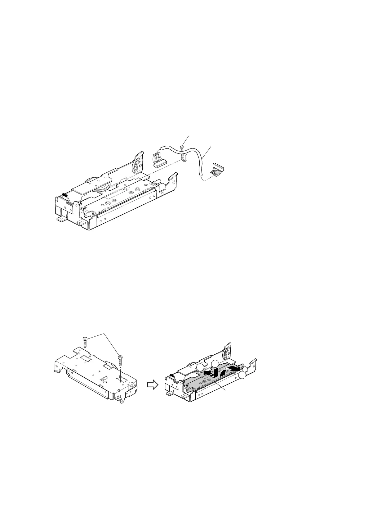
6. Cut the “Wire Tie” and detach the “SA Head Cable”.
7. Remove 2 screws (PH, M3x10).
8. While pressing down the “SA Plate Holder Head” block (), slide it to the rear until it stops ().
Since the “SA Plate Holder Head” comes off the frame, take it out of the frame ().
* The front part of the “SA Plate Holder Head” is connected to the frame, but its rear side is
free. So, the rear end can be lowered. When the “SA Plate Holder Head” block is moved to
the rearmost position with the rear end lowered, the front part of the “SA Plate Holder Head”
comes off the frame. Note that the “SA Plate Holder Head” block can be moved to the
rearmost position as 2 screws (BH, M3x12) have already been removed in Step 7.
9. Pull out the “Spacer Adjust Head Angle” from the “SA Plate Holder Head” block, remove 2
screws (BH (N), M3x6 (NI)), and detach the “Plate Label Protect” from the “SA Plate Holder
Head”.
10. Remove the “Spring Head L” and “Spring Head R”.
Wire Tie
SA Head Cable

 Loading...


