Chapter 2 Operating Principles
2-1. Operation of Each Mechanism
CL-S400DT 2-10
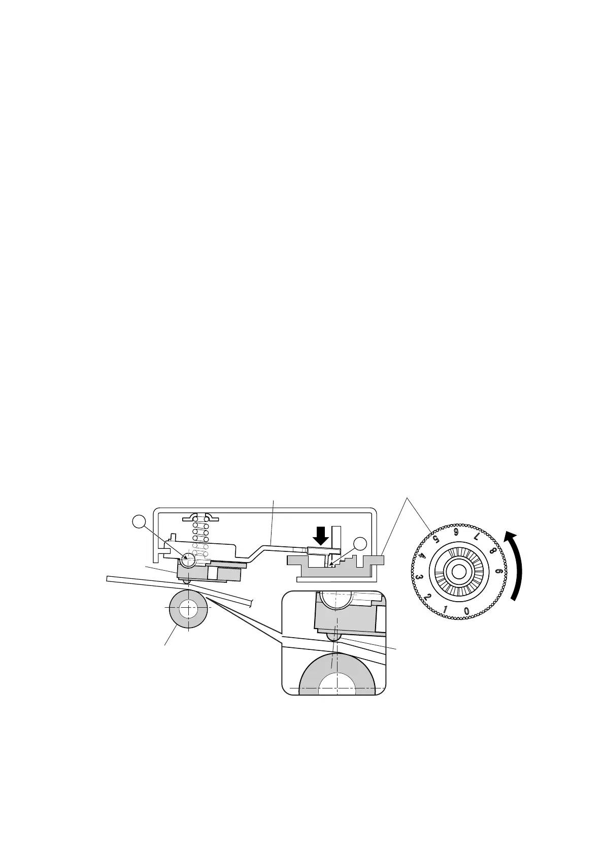
2-1-6. Media Thickness Adjustment Mechanism
The major components of the media thickness adjustment mechanism are:
(a) SA Plate Holder Head
(b) Cam Adjust Head Angle (Media thickness adjustment dial)
According to the thickness of media, the optimum position of the thermal element for printing varies
a bit. The media thickness adjustment mechanism is used to set the thermal element position
against the “SA2 Platen” to an optimum position by rotating the “SA, Head” around the supporting
point “B” shown in the figure below.
When thick media is used (tag paper):
When thick media is used, the optimum position of the thermal element will move toward the left a
little from the center of the “SA2 Platen”, viewing from the right side of the “SA2 Platen”. As the
optimum position varies according to thickness of media, it is necessary to adjust the Media
thickness adjustment dial from "1" to greater number to obtain an optimum position.
The end “A” of the “SA Plate Holder Head” is contacting with the cam part of the “Cam Adjust Head
Angle” (Media thickness adjustment dial). Therefore, as the dial is turned, the “SA Plate Holder
Head” moves up and down along the cam part. (Note that the supporting point of the “SA Plate
Holder Head” is “B” shown in the figure.)
As the “SA Plate Holder Head” is turned around the supporting point “B”, the “SA2 Head” that is
assembled with the “SA Plate Holder Head” is also turned. Thus, by turning the dial right and left,
the thermal element of the “SA2 Head” is moved back and forth a little.
When the Media thickness adjustment dial is turned toward a larger number, the end "A" of the “SA
Plate Holder Head” lowers more, and the thermal element moves to the left from the center of the
“SA2 Platen”, viewing from the right side of the “SA2 Platen”.
Cam Adjust Head Angle
SA Plate Holder Head
A
SA2 Platen
SA2 Head
B
Thermal element
Supporting point
[Thick media
toward dial No. 9
]
Media
(Media thickness adjustment dial)

 Loading...


