Chapter 3 Disassembly and Maintenance
3-6 Disassembly, Reassembly and Lubrication
3-15 CL-S400DT
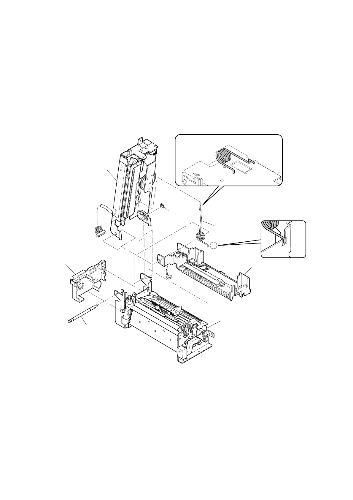
1
Cover Cable
Shaft Hinge Frame
E-Ring, 3
Spring Pop Up
SA Guide Paper U
SA Guide Paper L &
SA2 Main Frame
SA2 Cover Frame
3-6-7. Disassembly of “SA Mechanism Frame”
1. Remove the “SA Cover”. Refer to “3-6-2 SA Cover and SA LCD PCB”.
2. Remove the “Case” from the main body. Refer to “
3-6-3 Case”.
3. Disconnect the “SA Mechanism Frame” from the “SA2 Base Frame”. Refer to “
3-6-4
Disconnecting “SA Mechanism Frame” from “SA2 Base Frame””.
4. Remove the “Cover Cable” to the left after releasing its 2 claws from the hooks.
5. Unhook one end of the “Spring Pop Up” with round nose pliers ().
6. Disengage the “E-Ring, 3” and pull out the “Shaft Hinge Frame” to the front.
* Now, the “SA Mechanism Frame” is disassembled three blocks (“SA2 Cover Frame”, “SA
Guide Paper U” and “SA Guide Paper L & SA2 Main Frame”).
Notes on reassembling:
• Insert the long end of the “Spring Pop Up” into the hole of the “SA2 Cover Frame” as shown in
the enlarged view.
• Securely hook the other end (shorter end) of the “Spring Pop Up” () on the concave portion of
the “SA2 Main Frame” as shown in the enlarged view.

 Loading...


