Hydraulics QUANTUM TIC
11-76 10/04
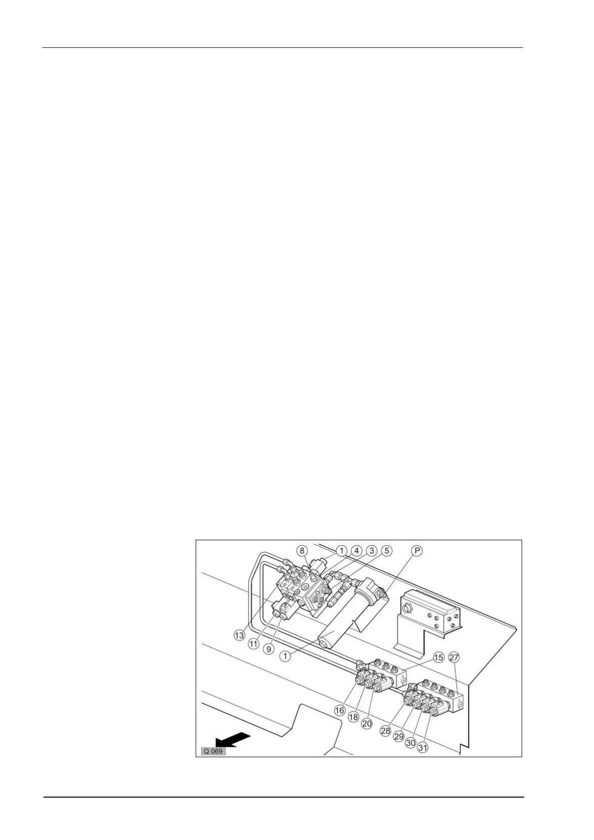
4.1 Circuit Diagram
P Tractor port (feed line)
T Tractor port (return line)
EW Tractor port (single acting)
1 Oil filter (110 l, 10 micro, resists diff. pressure of 30 bar)
2 Oil pressure switch 2 bar (normally open contact)
3 Connecting plate, BUCHER LU 08 PO OM 22
4 Circulation and pressure relief valve, Bucher LU 08 SBL-OM 22
5 Circulation valve spool
6 Orifice plate ø 0.8 mm, 0.6 l/min. control oil
6a LS port (load sensing)
7 Shut-off screw (closed hydraulic system, e.g. John Deere)
8 Pressure relief valve (p = 200 bar)
9 4/3 way proportional solenoid valve,
Bucher LP O8 E 4D 6363 OM 18 G12/12
10 Non-return valve
11 Load change valve
12 4/3 way solenoid valve, LM 08 E 4D 1010 OM 18612 (10 l/min.)
13 Connecting plate, BUCHER LU 08 PUT OM 22
14 Hydraulic motor, DANFOSS OMR 125 or OMR 160
14a Eaton 2-speed floor conveyor hydraulic motor 80/160 cm³
15 Seated valves, right block
16 2/2 way lower articulated drawbar solenoid valve
17 Articulated drawbar hydraulic cylinder
18 2/2 way close knife frame solenoid valve
19 Knife frame hydraulic cylinder
20 2/2 way open tailgate solenoid valve
21 Oil pressure switch 150 bar (normally open contact)
22 Tailgate hydraulic cylinder
27 Seated valves, left block
28 2/2 way raise articulated drawbar solenoid valve
29 2/2 way open knife frame solenoid valve
30 2/2 way close tailgate solenoid valve
31 2/2 way raise/lower pick-up solenoid valve
34 Couplers
35 Pick-up hydraulic cylinder
36 Orifice plate
M1 Floor conveyor forward solenoid coil
M2 Pressure port B solenoid coil
M3 Pressure port A solenoid coil