Electric System QUANTUM TIC
12-28 10/04
3.0 QUANTUM 4500 P / 5500 P / 5500 P-16 / 5500 P-18 / 5500 GT /
6500 P / 6800 P
3.1 Circuit Diagram
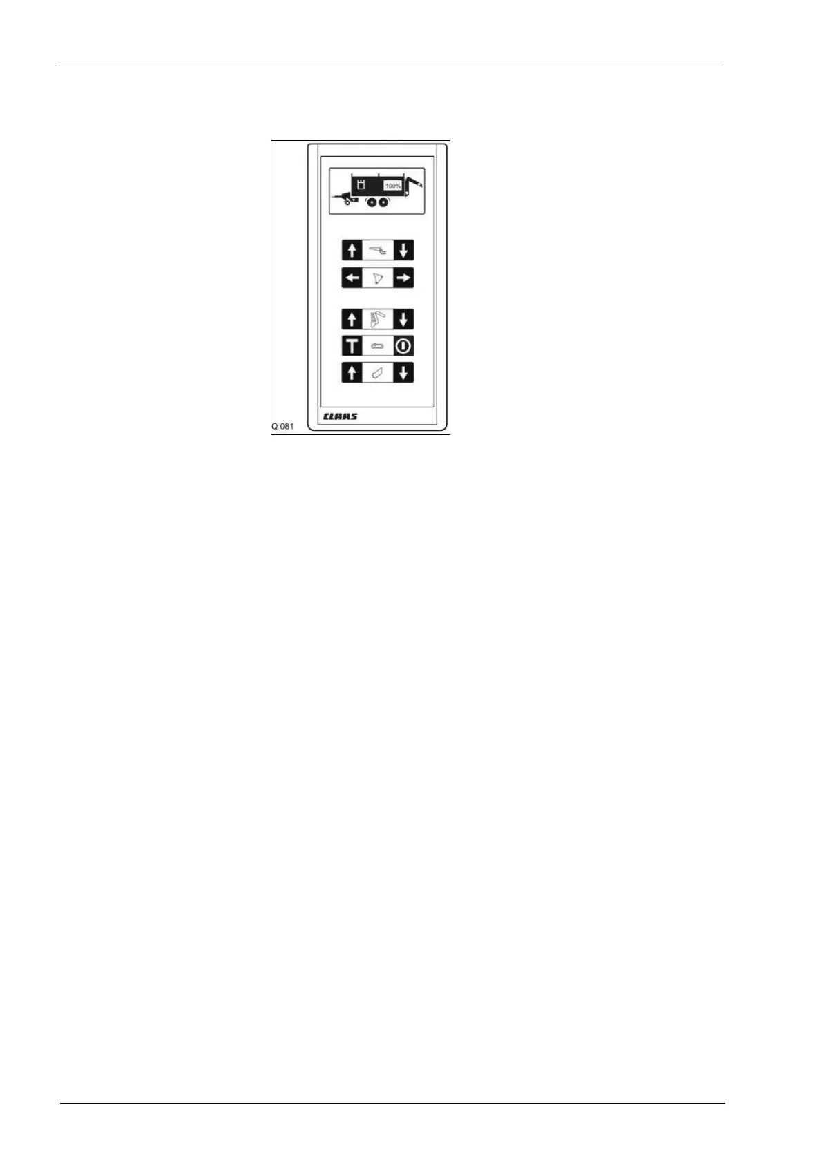
A Raise articulated drawbar pushbutton
B Lower articulated drawbar pushbutton
C Close knife frame pushbutton
D Open knife frame pushbutton
E Open tailgate pushbutton
F Close tailgate pushbutton
G Floor conveyor ON/OFF pushbutton when loading, tailgate must be
closed.
H Floor conveyor ON/OFF pushbutton when unloading, tailgate must be
open.
J Raise pick-up pushbutton
K Lower pick-up pushbutton
L Indicator light (green), pick-up bottom – floating position
M Indicator light (red), knife frame open
N Indicator light (flashing red), tailgate closed
O Indicator light (flashing green), tailgate open
P Light field (hydraulic system), lights up in red for approx. 3 sec., ready for
operation, oil circulating
R Light field (100%), flashing red – wagon full or tailgate open
1 Key button housing
2 24-pin plug connector, between lid and box
3 14-pin plug connector, designation of wire colours on the board
4 Distributor box
5 Connection of wiring loom to key button housing
6 Connection of wiring loom to power supply from tractor
7 3-pin plug connector
8 16 A fuse
9 Connection of wiring loom to knife frame reed switch
10 Knife frame reed switch
11
12 Connection of wiring loom to tailgate and wagon full reed switch …