Group 19, Motor Controls
19-1-6 • Description SM 765, Sep ’06
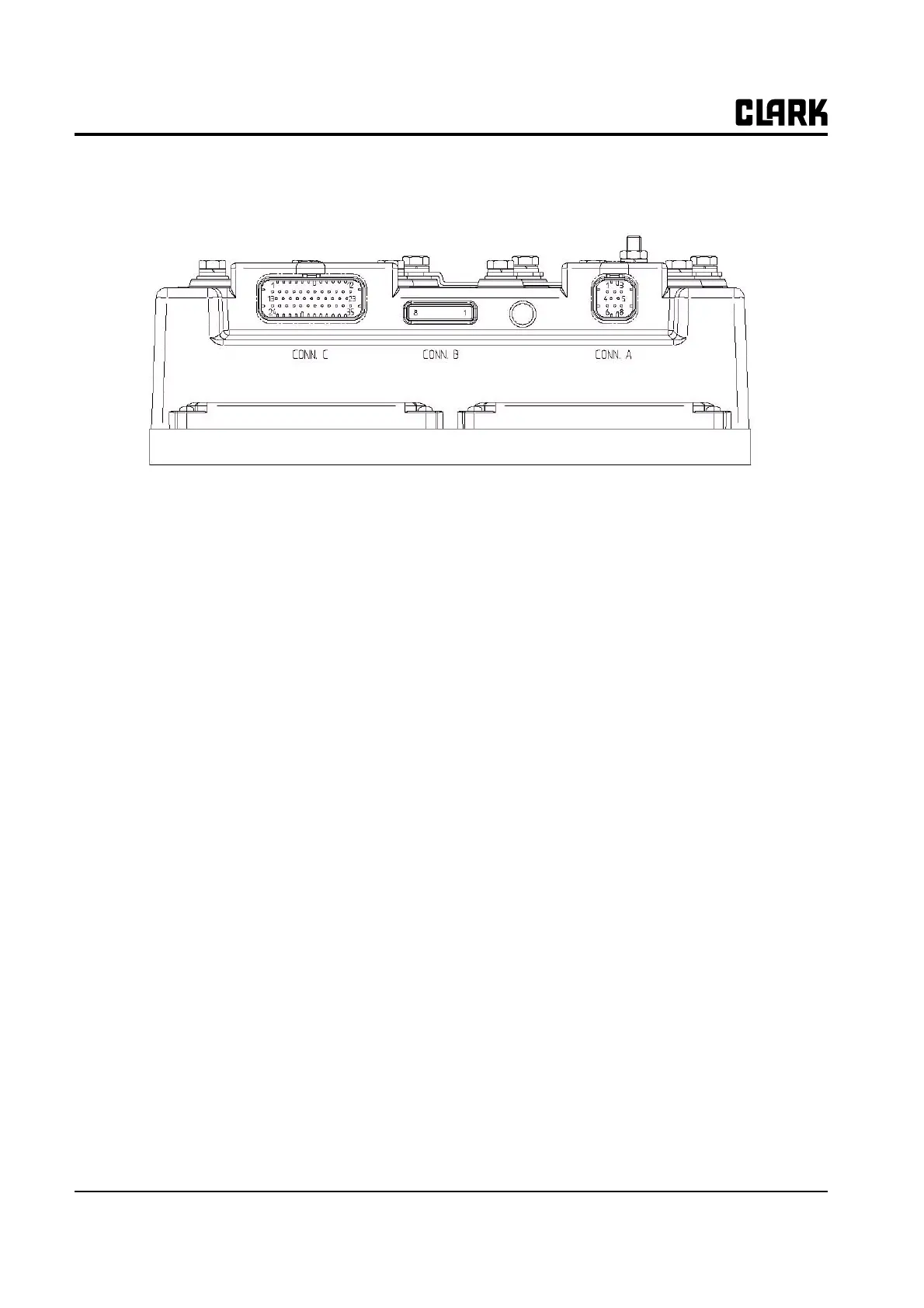
Description of Connectors - DualAC2(Power)
A1 CAN H High level CANBUS
A2 CANT H CANBUS termination output, 120 ohm internally connected to CAN_H. Connect to
CAN_L_OUT to insert termination.
A3 CAN_POS Positive of CAN circuit; to be used in case of optoisolated CANBUS
A4 CAN_L_OUT Low level CANBUS: to be used as repetition for CAN_L line or to be connected to CANT_H
to insert termination resistance
A5 CANT_L CANBUS termination output, 120 ohm internally connected to
CAN_L. CAN Connect to CAN_H_OUT to insert the termination.
A6 CAN_L Low level CANBUS.
A7 CAN_H_OUT High level CANBUS: to be used as repetition for CAN_H line or to be connected CANT_L to
insert termination resistance
A8 CAN_NEG
CANBUS
Negative of CAN circuit, to be used in case of optoisolated
B1 PCLRRXD Positive serial reception.
B2 NCLRRXD Negative serial reception.
B3 PCLRTXD Positive serial transmission.
B4 NCLRTXD Negative serial transmission
B5 GND Negative handset power
B6 +12 Positive handset power
B7 FLASH
B8 FLASH
C1 PENC_R Positive of the right motor encoder power supply (+12V).
C2 NENC_R Negative of the right motor encoder power supply
C3 KEY Connected to +Batt through a micro switch and a 10A fuse in series
C4 CM Common of FW / REV / HB / PB / SEAT / ENABLE micro switches
C5 Seat Seat presence input; active high.
C6 FORWARD Forward direction request input; active high.
C7 REVERSE Reverse direction request input; active high.