Group 20, Drive Axle
SM 765, Nov ’06 Adjustment • 20-6-3
Adjustment of thrust needle bear-
ing gap
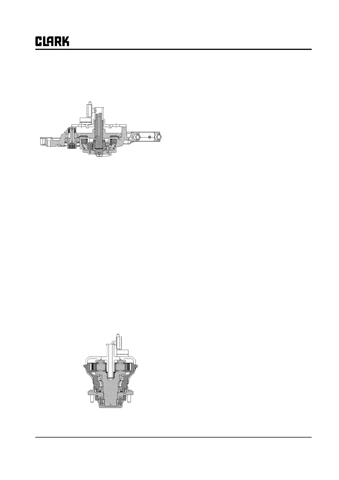
Figure 18. Drive axle assembly
Required tool for setting
− Measuring jig
− Dial gauge
How to measure the gap
• Install the assembled axle ass'y to the exclusive jig
or flat bottom.
• Set the measuring jig as shown in the figure 18.
• Place the dial gauge on the measuring jig and mea-
sure the stage differences of jig.
• Record the value that the dial gauge shows.
• Install the assembled wheel ass'y to the exclusive
jig or flat bottom as above method.
• Set the measuring jig to axle end assembly as
shown in the figure 19.
Figure 19. Axle end assembly
• Record the value that the dial gauge shows.
• Calculate the stage differences of drive axle and
wheel, and set the gap of shaft direction.
• Set the thrust needle bearing based on gap specifi-
cation.
(Specification : 0.05~0.1mm)
Calculation of measured value and shim
adjustment
• Adjust it by summing the measured values of
wheel and drive axle and deducting the existing
shim (3t).
• If the summed value is "0", set the gap with
0.1mm.
Apply the different spacer based on the measured
value (for example, 3T, 3.1T, 3.2T)