Group 25, Steering Column and Gear
25-5-4 • Steering Gear Overhaul SM 765, Dec ’06
Parts Inspection
Inspect all parts for damage, cracks, broken parts, dam-
aged threads, corrosion or erosion of surfaces, worn spots,
nicks or scratches.
Check all mating surfaces. Replace any parts that have
scratches or burrs that could cause leakage. Discard all old
seals and replace with new ones.
Clean all metal parts in clean solvent. Blow dry with air.
Do not wipe dry with cloth or paper towel because lint or
other matter can get into the hydraulic system and cause
damage. Do not use a coarse grit or try to file or grind
these parts.
If parts are left exposed, cover them with a clean cover to
prevent airborne dust from collecting on them.
Reassembly
Refer to Service Parts Book when ordering replacement
parts. A good service policy is to replace all old seals with
new seals at overhaul.
N
TE
Lubricate all seals (with exception of new
quad ring seal) with clean petroleum jelly
such as Vaseline.
Do not use excessive lubricant on seals for
meter (gerotor) section.
Make sure all parts are clean and free of
dust. Before assembly, lightly coat all internal
metal parts with oil.
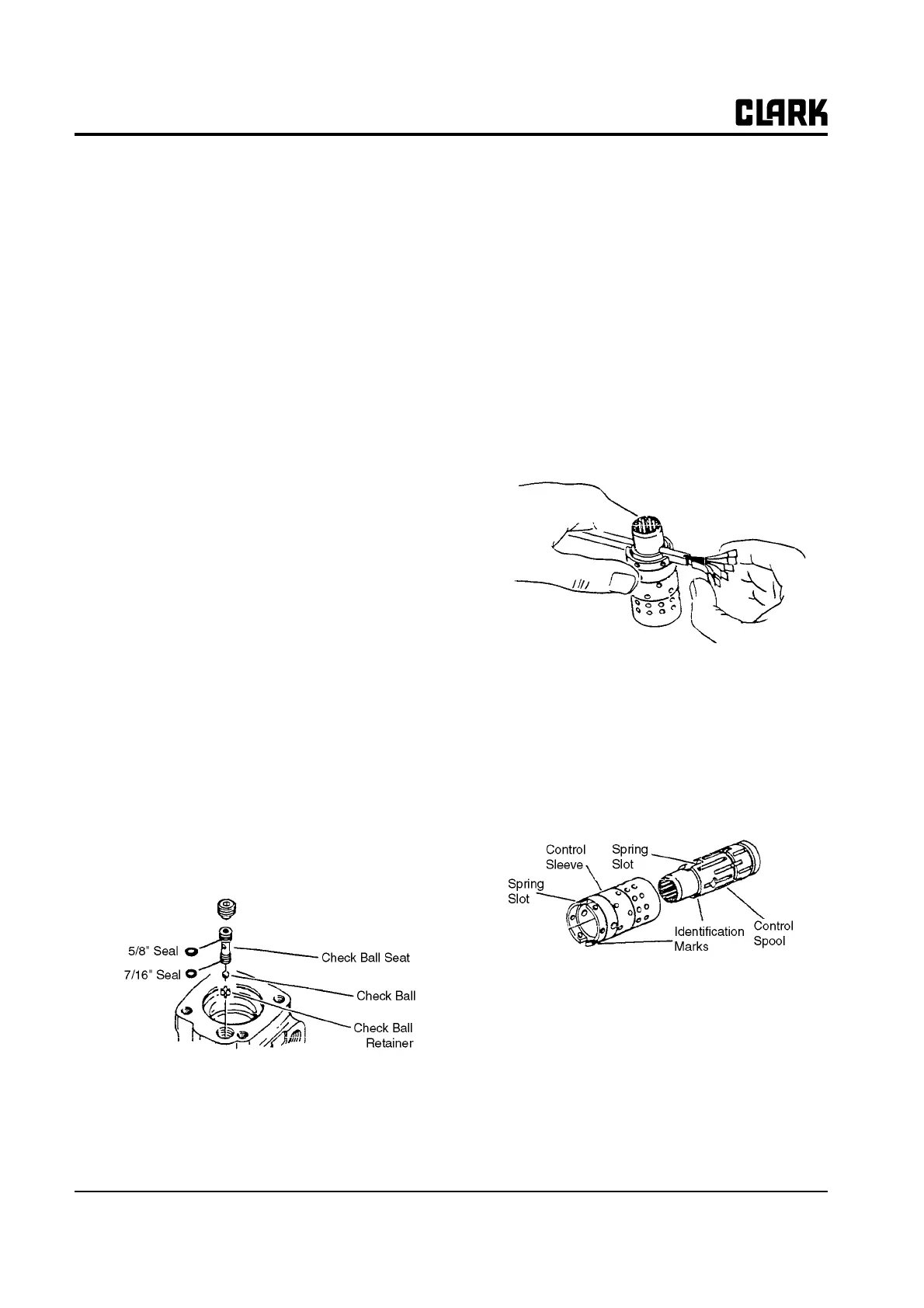
Control End
1. Use a needle-nosed pliers to lower check ball retainer
into check valve hole of housing. Make sure retainer
is straight (not tilted on edge) in housing.
2. Install check ball in housing.
3. Lubricate 5/8-inch diameter seal and 7/16-inch diam-
eter seal. Install seals on check ball seat, as above.
4. Lubricate check ball seat and seals thoroughly before
installing seat in housing. When installing seat do not
twist or damage seals. Install check ball seat in hous-
ing; insert open end of seat first. Push check ball seat
to bottom of hole.
5. Install set screw. Use a 5/16-inch Allen wrench to
torque set screw to 11 N⋅ m (100 in-lb; 8.3 ft⋅lb). To
prevent interference of parts, make sure top of set
screw is slightly below housing mounting surface.
6. Assemble spool and sleeve carefully so that the
spring slots line up at the same end. Rotate spool
while sliding parts together. Some spool and sleeve
sets have identification marks ; align these marks.
Test for free rotation. Spool should rotate smoothly
in sleeve with finger tip force applied at splined end.
7. Bring spring slots of both parts in line and stand parts
on end of bench. Insert spring installation tool (avail-
able as Part No. 6000057) through spring slots of
both parts. Position three pairs of centering springs
(or two sets of 3 each) on bench so that extended
edge is down and arched center section is together. In
this position, insert one end of entire spring set into
spring installation tool, as shown.
On those units which use the low torque centering
springs, there are two pairs of centering springs (or
two sets of each) and one pair (two) spring spacers.
The spring spacers are installed together between the
two sets of centering springs. The installation proce-
dure is the same as that used on the standard (three
pairs of centering springs) units.