Group 19, Motor Controls
SM 765, Sep ’06 Description • 19-1-7
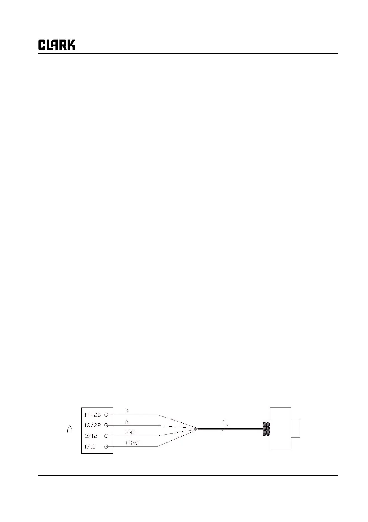
Encoder Installation
In order to control the AC motors with the ZAPI controller an incremental encoder is installed with 2 phases shifted at
90°. The encoder power supply is 12V
Connection of encoder with open collector output; +12V power supply.
C8 ENABLE Traction request input; active high.
C9 PB Pedal brake request input; active high.
C10 SR / HB Speed reduction or hand brake input; active low (micro switch open).
C11 PENC_L Positive of the left motor encoder power supply (+12V).
C12 NENC_L Negative of the left motor encoder power supply
C13 PHA_R Right motor encoder phase A.
C14 PHB_R Right motor encoder phase B.
C15 NPOTST Negative of steering potentiometer (-Batt)
C16 PPOTST Positive of steering potentiometer (+5V)
C17 CPOTST Steering potentiometer wiper signal.
C18 CPOTB Brake potentiometer wiper signal.
C19 NPOTB -Batt.
C20 NPOT Negative of traction accelerator (test for wire disconnection)
C21 CPOT Traction potentiometer wiper signal.
C22 PHA_L Left motor encoder phase A.
C23 PHB_L Left motor encoder phase B.
C24 NTHERM_R Negative of right traction motor temperature sensor.
C25 PTHERM_R Right traction motor temperature signal.
C26 NLC Output of main contactor coil driver (drives to -Batt)
C27 PLC Positive of main contactor coil.
C28 NBRAKE Output of electric brake coil (drives to -Batt, Maximum current 3A)
C29 PBRAKE Positive of electromechanical brake coil.
C30 PAU Xpositive of auxiliary load.
C31 NAUX Output of auxiliary load driver (drives to _Batt).
C32 -BATT
C33 PPOT Traction potentiometer positive, 5V output, use load > 1K omh.
C34 NTHERM_L Negative of left traction motor temperature sensor.
C35 PTHERM_L Left traction motor temperature sensor.
C11/C1 +12V Positive of encoder power supply.
C12/C2 GND Negative of encoder power supply.
C22/C13 A: Phase A of the encoder
C23/C14 B: Phase B of the encoder