Group 30, Hydraulic Control Valve/Lift Circuit
30-5-4 • Hydraulic Control Valve Removal and Replacement SM 765, Sep ’06
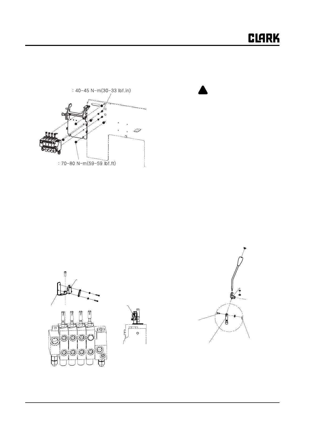
Reinstall Valve
1. Reinstall valve and valve plumbing.
Lift and Tilt Pump Switches
Adjustment
1. Turn key switch to the OFF position.
2. Loosen switch mounting screws.
3. Adjust switch to activate after 2 mm (0.08 in.) of
spool travel from neutral.
4. Tighten mounting screws.
Operational Checks
1. Operate the truck and hydraulic system. Check the
system for leaks.
WARNING
!
Do not use your hands to check for hydraulic
leakage. Use a piece of cardboard or paper to
search for leaks. Escaping fluid under pres-
sure can penetrate the skin causing serious
injury. Relieve pressure before disconnecting
hydraulic or other lines. Tighten all connec-
tions before applying pressure. Keep hands
and body away from pinholes and nozzles
which eject fluids under high pressure.
If any fluid is injected into the skin, it must
be surgically removed within a few hours by
a doctor familiar with this type injury or
gangrene may result.
2. Check the operation of the valve and hydraulic sys-
tem by moving the valve control levers to the various
positions. The levers must operate smoothly with no
binding. When released from any working position,
the levers must return sharply to their neutral posi-
tions.
If valve spools do not moved or return to correct
position for full function of lift, tilt, or auxiliary cyl-
inders:
a. When inserting the pin to the lever, check it is
smoothly inserted.
3. Refer to Section 4, “Hydraulic System Pressure-
Check” if valve was disassembled or overhauled.
Torque to
Torque to
Switch shown
mounted
Micro Switch
Switch Mounting
Bracket
Clevis Pin
Cotter Pin
Valve Spool