Group 13, Wiring, Switches, and Instruments
SM 765, Sep ’06 Switches and Sensors • 13-4-3
Program Adjustment
CAUTION
!
Before any adjustments are done, safely jack
up the truck, block the drive wheels off the
floor and disconnect the battery.
Use the following method to program the accelerator con-
trol to the contol panel with the handset:
(Detailed handset operation instructions are in Group 19.)
• Disconnect the dash display harness from the con-
trol panel
• Plug handset into plug "B" of the control
• Plug in the battery
• Turn the key switch On
• Handset will go through startup and display soft-
ware version
• Press the “ENTER” button
• Display will read "MAIN MENU' "PARAMETER
CHANGE".
• Press the “ROLL UP” button five times
• Display will read "MAIN MENU" “PROGRAM
VA C C ”
• Press the "ENTER" button
• Display will read "VACC SETTINGS"
• Press the "ENTER” button
• Display will read "MIN VACC MAX"
• Move the directional lever to Forward position
• Depress the accelerator pedal to the floor and than
release slowly
• Move the directional lever to the Reverse position
• Depress the accelerator pedal to the floor and than
release slowly
• Press the "ENTER" button
• Press the “OUT” button
• Display will read "ARE YOU SURE"
"YES=ENTER" "NO=OUT"
• Press "ENTER" button (this stores the value for
MIN and MAX accelerator voltage)
• Display will show new settings
• Press the “OUT” button
• Display will read "MAIN MENU" “PROGRAM
VA C C ”
• Press "OUT button
• Display will show software version
• Turn the key switch Off and remove the tester cord
from the control
• Plug the dash display harness into the "B" plug of
the control
• Lower truck to the ground and test drive truck
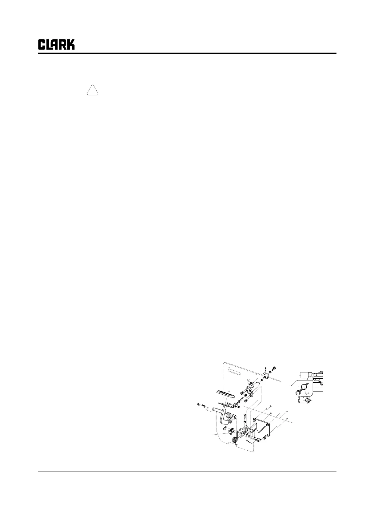
Brake Switches
Service Brake Switch Description
The foot brake switch is on the brake link end, under the
flow plate. The switch operates when it is released by the
brake pedal lever during braking. Depressing or releasing
the switch operates a set of contacts that alternate from
open to closed to activate the Pedal Braking function of
the control. This function uses the motor to help bring the
truck to a controlled stop.
Service Brake Switch Adjustment
Adjust the switch so that it “clicks” just before the end of
pedal “freeplay” (the lag between pressing the brake and
operating the master cylinder, covered in Group 23).
Adjust switch as follows.
1. Turn key switch OFF.
2. Make sure freeplay is properly adjusted as described
in Group 23.
3. Loosen brake switch mounting screws.
4. Rotate switch against pedal until switch trips. (A
click can be heard.) Tighten mounting screws.
5. Check operation of switch by depressing brake pedal.
Switch should actuate just before the end of freeplay
(at which time you feel resistance in the pedal caused
by the master cylinder beginning to operate.)
Capscrew height
control
Brake
Switch