Group 30, Hydraulic Control Valve/Lift Circuit
SM 765, Sep ’06 Hydraulic Control Valve Removal and Replacement • 30-5-3
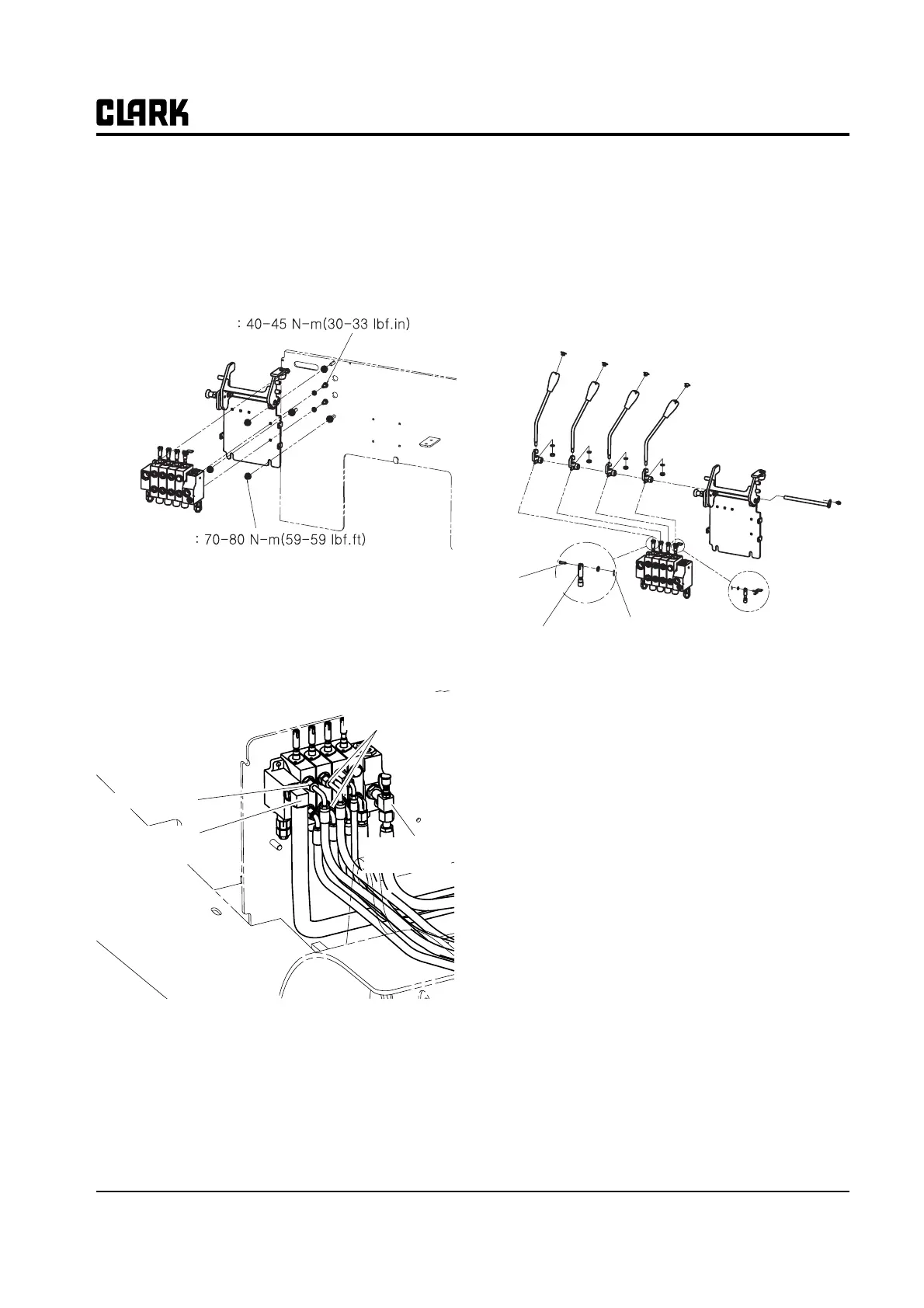
Hydraulic Control Valve Replacement
Valve Replacement
1. Install the main valve on the valve mounting bracket.
2. Install the valve mounting bracket on the frame.
3. Install the hydraulic lines on the proper ports. Make
sure all lines are clean, arerouted correctly in the
truck, and are not kinked. Torque fittings according
to “Hydraulic Fitting Tightening Procedure” in
Group 40.
Control Valve Linkage Reassembly
1. Insert the clevis pins through the rod-end clevises
and valve spools of the lift and tilt spools (and auxil-
iary-lever rods and spools where applicable) and
secure with the cotter rings. Rotation of the valve
spools is required to allow insertion of the clevis
pins. Rotate spools back so all pins are in line.
N
TEN
TEN
TEN
TEN
TE
The illustration above and system specifica-
tion torques also apply for auxiliary hydrau-
lic functions, such as a side-shifter or rotator.
2. Set the interval of lever, then tighten the nuts under
the lever with torque of 40-50Nm(30-33ft.lb).
Torque to
Torque to
To Upringt
Feed Line
from Pump
Tilt Cylinder
Lines
Return Line
to Sump
Clevis Pin
Cotter Pin
Valve Spool