Group 34, Uprights
SM 765, Nov ’06 Upright Inspection • 34-3-3
Hydraulic System
Inspect the upright hydraulic system components for:
• Damage or wear on all hoses and hydraulic tubes.
• Leaks on hoses, fittings, or valves.
• Leakage on the cylinders.
• Excessive drift in lift or tilt operations.
Extended Inspection
The extended inspection should be performed whenever
the basic visual inspection indicates upright problems, as
specified for PMs, or at least every 2000 hours.
Forks
Forks have a limited service life because of wear and
fatigue. Forks should be tested every 50-250 hours using a
visual inspection, a fork thickness check, a fork bending
check, and a fork gap check. If replacement is necessary,
always replace the pair to ensure fork integrity.
Fork Alignment
1. Park the truck on a flat, even surface, tilt upright to
vertical position, and set forks 25-50 mm (1-2 in)
above the ground.
2. Compare fork arms to be sure they are straight, on
the same plane (level), and the same length.
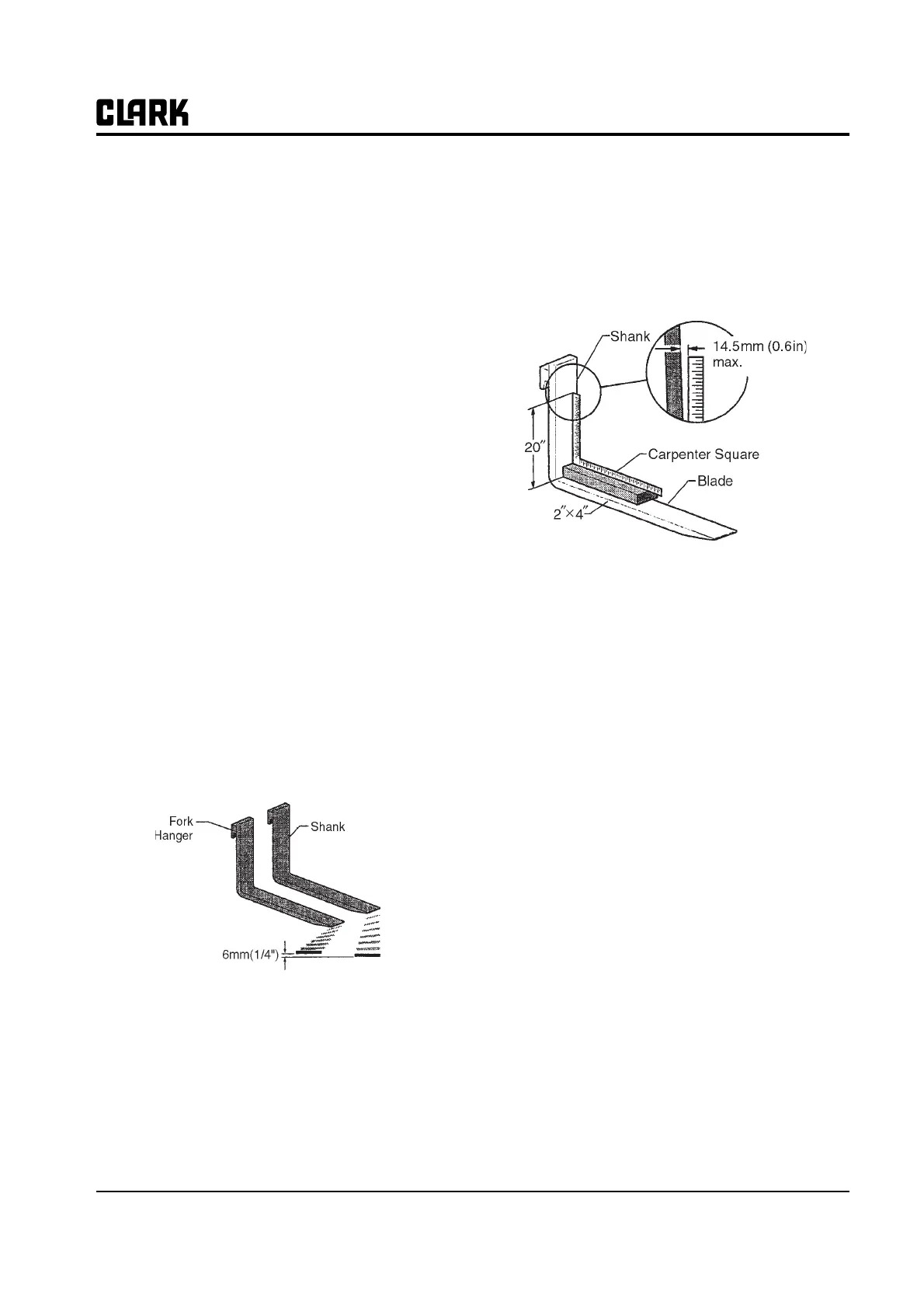
3. Measure the distance from the fork tips to the
ground. The height difference between the forks tips
should be no more than 6mm(1/4in).
Fork Arm Height
4. If the fork tips are not aligned within the specified
6mm (1/4in) difference, the cause of the problem
must be determined and corrected before returning
the truck to service. If replacement is necessary,
always replace the forks in a set.
Fork Bending
Overloading, glancing blows against solid objects, or
picking up loads unevenly can bend or twist a fork. Use
the following procedure to check for fork bending.
1. Place a 50 x 100 x 610 mm (2 x 4 x 24 in) wood
block flat on the fork. Make sure the block is not rest-
ing on the heel radius.
Fork Bending Check
2. Set a carpenter’s square on the block against the fork
shank
3. Check the fork 508 mm (20 in) above the blade to
make sure it is not bent more than 14.5 mm (0.6 in) at
the maximum.
4. If blades are bent over the 14.5 mm (0.6 in) allow-
ance they should be replaced as a set.
See Section 7, “Fork and Carriage Removal and Replace-
ment,” for procedures to remove and replace the forks.
Fork Fatigue
Fatigue cracks normally start in the heel area or on the
underside of the top hanger. If cracks are found, the fork
should be replaced. Dye penetrants or magnaflux can be
used for a more accurate inspection.
Fork Wear and Heel Wear
Industrial Truck Association (ITA) standards require that
a fork be removed from service when the blade or heel
thickness is reduced by 10% over its original thickness. If
the heel is 10% smaller than the arm, the load capacity
could be reduced by 20%. A 5,000-pound (2272 kg)
capacity fork with 10% wear can only safely handle 4,000
pounds (1818 kg).
Use of fork wear calipers are recommended (Clark part
number 1803641) to gauge fork wear as follows:
1. Use the outside jaws of the caliper to measure fork
thickness in the shank area of the fork.