Group 19, Motor Controls
19-1-10 • Description SM 765, Sep ’06
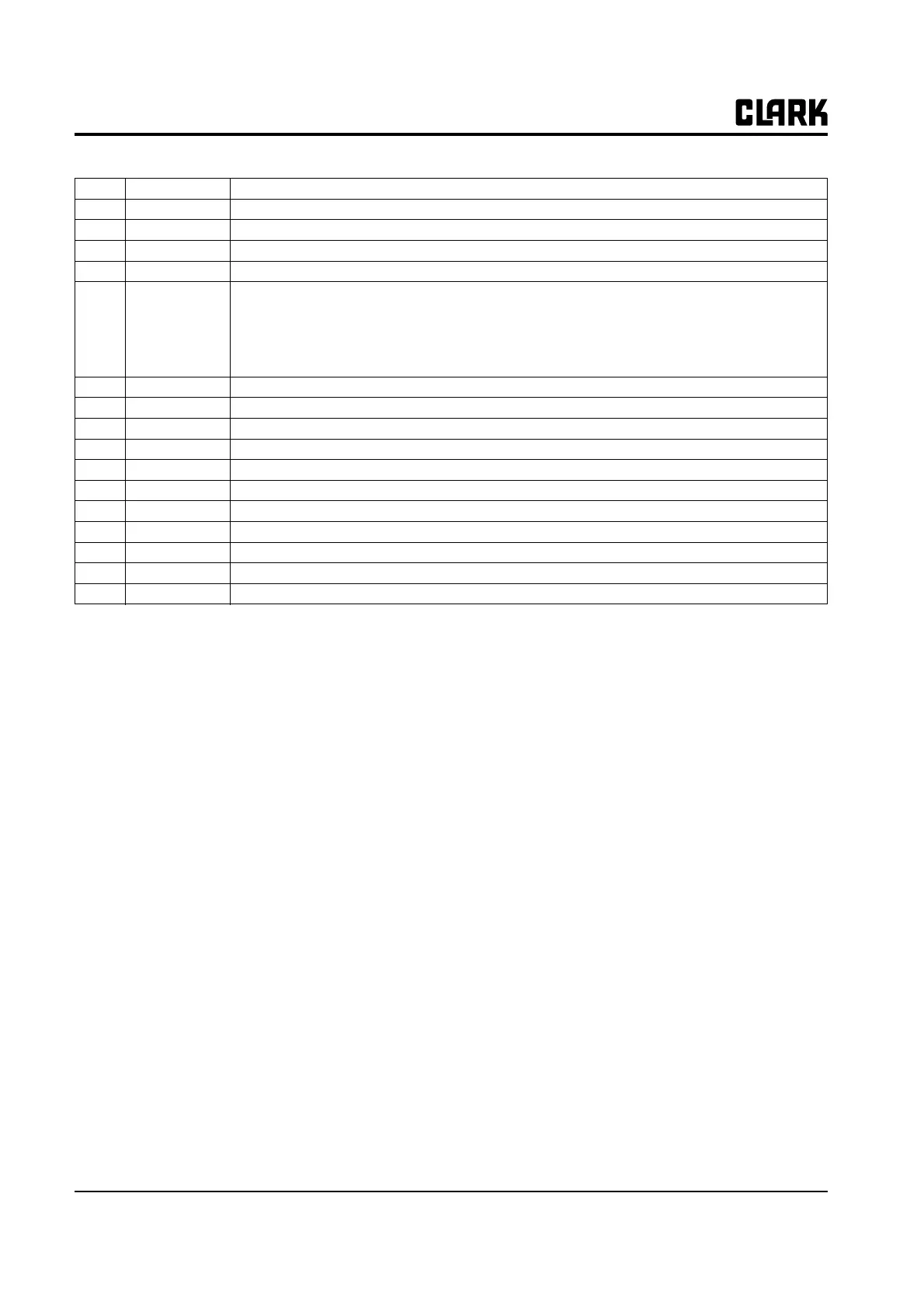
C2 CAN-L-OUT Low level CAN-BUS voltage I/O.
C3 CAN-H High level CAN-BUS voltage I/O.
C4 CAN-H-OUT High level CAN-BUS voltage I/O.
D1 -BATT -Batt.
D2 MODE This input allows the customer to select the software for traction or
lifting application.
Configuration:
MODE: Open (not connected) Traction inverter
MODE: Close (connected with A5) Pump inverter
E1~E6 Incremental ENCODER connector (see chapter 3.6).
F1 PCLRXD Positive serial reception.
F2 NCLRXD Negative serial reception.
F3 PCLTXD Positive serial transmission.
F4 NCLTXD Negative serial transmission.
F5 GND Negative console power supply.
F6 +12 Positive console power supply.
F7 FLASH Must be connected to F8 for the Flash memory programming (if used).
F8 FLASH Must be connected to F7 for the Flash memory programming (if used).