Group 30, Hydraulic Control Valve/Lift Circuit
SM 765, Nov '06 Hydraulic System Pressure Checks and Adjustments • 30-4-1
CAUTION
!
SAFE PARKING. Before working on truck:
1. Park truck on a hard, level, and solid
surface, such as a concrete floor with no
gaps or breaks.
2. Put upright in vertical position and fully
lower the forks or attachment.
3. Put all controls in neutral. Turn key
switch OFF and remove key.
4. Apply the parking brake and block the
wheels.
Relief Pressure Checks
Following is the procedure for checking main hydraulic
valve lift pressure and auxiliary relief pressure (if the
truck is equipped with an auxiliary component).
Hydraulic system relief pressure setting may be checked
using a Mica Quadrigage (Clark Part No. 923770) or with
a conventional pressure gauge with suitable pressure
range calibration. To cover all models of the truck, a
gauge with capacity range of 0 to 34,475 kPa minimum (0
to 5000 psi) is recommended.
WARNING
!
HYDRAULIC FLUID SAFETY. Keep all
hydraulic ports and components clean. Wipe
the area on the pump around the diagnostic
check port completely clean to prevent any
contamination from entering the hydraulic
system.
When checking the hydraulic system, do not
use your hands to check for leakage. Use a
piece of cardboard or paper to search for
leaks. Escaping fluid under pressure can pen-
etrate the skin causing serious injury. Relieve
pressure before disconnecting hydraulic or
other lines. Tighten all connections before
applying pressure. Keep hands and body
away from pinholes and nozzles which eject
fluids under high pressure.
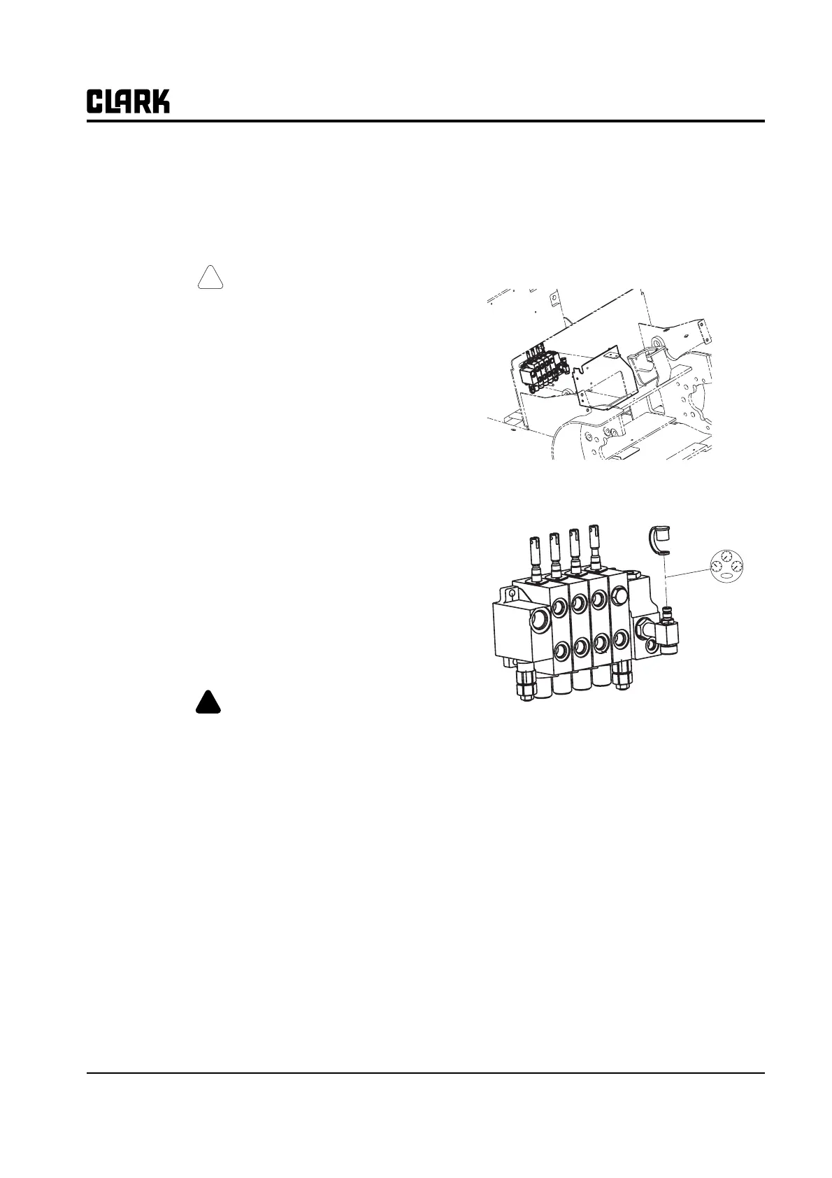
1. Remove the covers enclosing the main hydraulic
valve to access the hydraulic system pressure diag-
nostic check port.
2. Remove the cap from the gauge port on the valve and
connect pressure gauge to the fitting.
N
TEN
TEN
TEN
TEN
TE
Use quick-disconnect adapter fitting, Clark
Part #913125.
3. Check main relief pressure: Turn key switch on,
move the lift control lever to full back lift relief posi-
tion. Hold lift control in relief position until pressure
reading is obtained, and then release. Gauge should
read 20,600 to 21,100 kPa (3988 to 3060 psi).
IMP
RTANT
Do not operate system in relief any longer
than required to read the pressure gauge.
4. Check auxiliary relief pressure: (Truck must have
auxiliary component and auxiliary section added to
main hydraulic valve.) Move the auxiliary control
lever to full back or forward relief position. Hold
auxiliary control in relief position until pressure
reading is obtained, and then release. Gauge should
read 13,700 to 14,200 kPa (1987 to 2060 psi).
Section 4
Hydraulic System Pressure Checks and Adjustments