Group 34, Uprights
34-3-10 • Upright Inspection SM 765, Nov ’06
WARNING
!
Keep clear of load and carriage when making
any checks or adjustments. Do not use the
upright to climb; use an approved platform.
4. Wait ten minutes and recheck the mark. Measure and
write down the distance the marks on the inner and
intermediate rails have drifted from the mark on the
outer rail.
5. If the rated load drift 50 mm (2 in) or more in the ten
minutes, read and follow the procedures presented in
“Drift Causes and Remedies.”
CAUTION
!
CAUTION
!
Test load must be stacked stably, not extend
beyond the pallet, and be secured on the pal-
let.
Drift Causes and Remedies
If drift of 50 mm (2 in) or more is evident under the rated
load, consider the following causes and remedies:
• The main hydraulic valve is misadjusted, worn, or
defective. Fluid is leaking past the valve and caus-
ing the upright cylinders to drift. See Group 30 for
hydraulic valve troubleshooting and service.
• Upright hydraulic circuit hoses or fittings are leak-
ing. Check the circuit components and repair as
necessary.
• Cylinder piston seals are worn, damaged, or defec-
tive allowing fluid past the piston causing drift.
• Primary cylinder or piston-type lift or secondary
cylinders have a check valve that allows oil to flow
back to the rod side of the cylinder. This check
valve may be clogged or defective. Inspect the
check valve for proper sealing and operation.
Consider rebuilding the cylinders if the first two remedies
in this list are not successful. See Section 5 for removal,
overhaul, and replacement procedures for primary and
secondary cylinders.
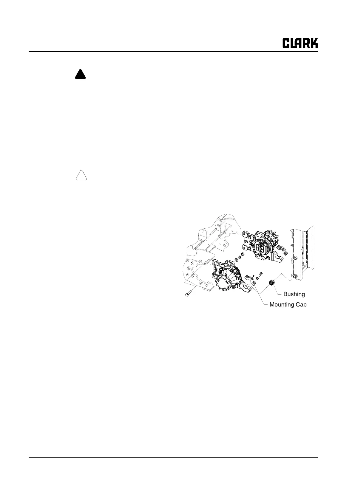
Upright Mounting Check
To check the Upright mounting:
1. Check for missing, broken, bent, or loose trunnion
cap fasteners. Replace any damaged parts.
2. Lift the upright 305-610 mm (1-2 ft) and tilt the
upright fully forward.
3. Check for Bushing or cap wear by inserting a feeler
gauge between the upright mounting cap and the
axle-mounting bearing surface.
• The gap should not exceed 0.75 mm (0.03 in).
• If the gap exceeds 0.75 mm (0.03 in) the bearing or
cap may need replacement.
See Section 8, “Upright Removal and Replacement,” for
procedures to remove and replace the bushing.