Group 34, Uprights
34-6-6 • Upright Chain Inspection, Adjustment, and Replacement SM 765, Nov ’06
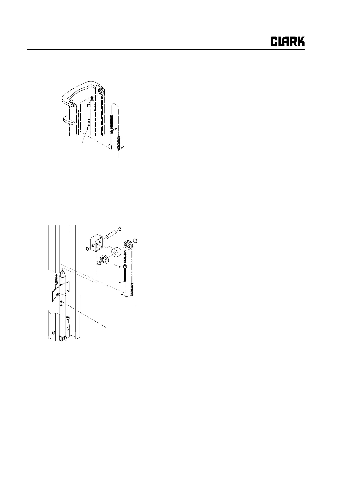
To adjust the cylinder lift chains on a TSU use the follow-
ing illustration and procedures:
1. Set the upright in the vertical position.
2. Break the jam nuts loose on the chain anchors.
3. Adjust the chain anchor adjustment nuts until the
bottom of the inner rail is within 2.5 mm (0.10 in) of
the bottom of the outer rail.
To adjust the primary cylinder lift chain on TSU and Hi-
Lo use the following illustration and procedures:
1. Fork-to-ground clearance:
a. Set the upright to vertical position.
b. Break the jam nuts loose on the chain anchors.
c. Turn the chain adjustment nuts until clearance
between forks and ground is 10-20 mm (0.40-
0.80 in).
IMP
RTANT
For all chain anchor adjustments:
• Threaded chain anchors must be left free to
pivot in mounting hole.
• Anchor cotter pin heads must be to the
inside of the upright.
• Torque jam nuts to adjustment nuts to
100-200 N⋅m (74-148 ft-lb).
• Make sure chain anchors are secured so
that no twist is evident in the chains.
2. Carriage roller position:
a. Raise carriage about 1 m (3.2 ft) and smear a
bead of grease on the bottom 75 mm (3 in) of the
inner rail in the area of the roller pattern.
b. Tilt upright fully back and completely lower.
c. Raise carriage again about 1 m (3.2 ft) and mea-
sure the distance from where the center of the
bottom carriage roller stopped to the bottom edge
of the inner rail. Distance should not be less than
20 mm (0.80 in) or chain length adjustment is
required.
3. Carriage stop-to-upright:
a. Lift upright to its full height and check for clear-
ance on the carriage safety stop.
b. If the carriage stop hits the upright stop, adjust
the chain anchor adjustment nuts out until there is
at least 3 mm (0.12 in) clearance between the
stops.
IMP
RTANT
The carriage stop must not be allowed to con-
tact the upright stop under any circumstance
during normal operations.
If all three chain length requirements listed above cannot
be met, the tire diameter may be out of the design range
allowance. Also, excessive tire wear will decrease carriage
stop clearance.
Oversized tires will reduce the bottom carriage roller
engagement on the inner rail when the carriage is in the
lowered position. The fork-to-ground clearance can devi-
ate from the 10-20 mm (0.40-0.80 in) allowance by a
small amount if necessary to maintain the safe 20 mm
(0.80 in) clearance of the bottom carriage roller to the
lower edge of the inner rail.
To inner rail
Adjust chain
length here
To carriage
Adjust chain
length here