Group PS, Periodic Service
PS-2-6 • Planned Maintenance SM 765, Nov ’06
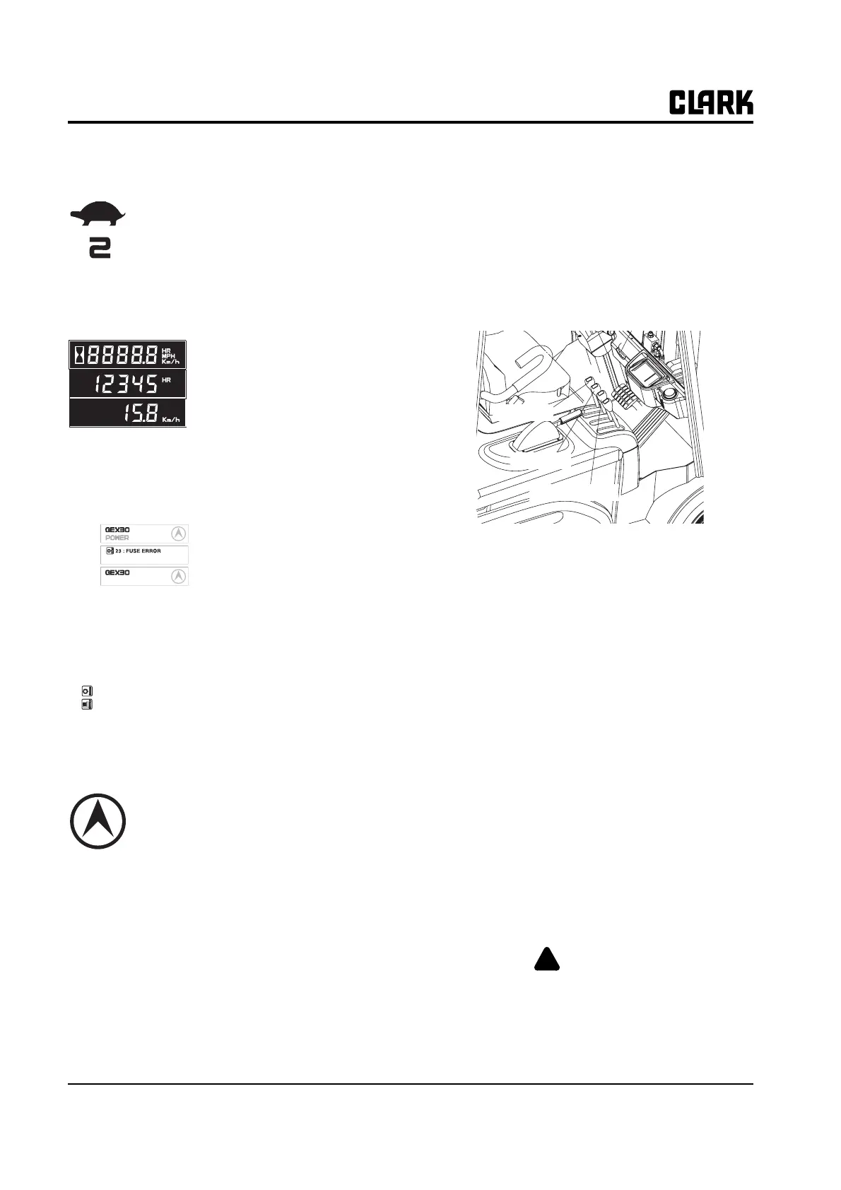
Slow-speed indicator (Turtle shaped)
The traveling speed of truck is limited to
set speed.
The upper mark is slow speed operating
icon, and the figure shows the limited
max. speed. (In upper example, the lim-
ited max. speed is 2km/h)
Hourmeter & Speed
• It displays the accumulated oper-
ating hour and traveling speed of
truck.
• When the traveling speed is less
than 0.5km/h, it displays the accu-
mulated operating hour.
• When the traveling speed is more
than 0.5km/h, it displays the traveling speed.
Message display
The model name, POWER
selection, travel direction, warn-
ing and error message are dis-
played.
• In normal operating condition:
Model name/POWER/Travel direction
• When several messages are simultaneously dis-
played, it will be displayed in the order of Error,
Warning and Normal condition.
• If many error conditions are
simultaneously occurred, the
priority 2 Errors will be displayed.
(The priority means Error number)
Travel direction icon
• It displays the traveling direction or angle of
steering wheel..
• The direction icon rotates in 10 degrees.
(Total 36 icon)
Error icon
• When error occurs this icon is displayed to distin-
guish the condition easily. When the error message
is displayed, this icon is simultaneously displayed.
3. Check Function Control Levers
• Gently pull back on the lift control lever. The pump
motor should turn on and the carriage should begin
to elevate.
• Release the control lever. It should return to neutral
without binding. The pump motor should turn off.
The control lever should not bind when moving it
to any position.
• Repeat procedures with tilt control lever. Forks
should tilt evenly and smoothly.
• If lift truck is equipped with an attachment, test the
auxiliary control lever for a correct function.
• Briefly operate the attachment.
4. Check Drive Motor (Brake) Cut-Off Switch
• Move the truck forward slowly. Slowly depress
brake pedal. Drive motor should cut off before the
brakes apply.
• If operation is not satisfactory, DO NOT operate
the truck. Take truck out of service and report con-
dition to designated authority.
5. Check Upright
• Note any excessive “slop” or “noise” in the
upright. It may indicate roller damage, or that
roller shimming, repair or adjustment may be
required.
6. Check Tilt Cylinder (Refer to Group 32 to do the
following)
• Perform drift test.
• Perform check and adjustment procedure.
• Check rod seal condition.
• Check mounting. Tighten as needed.
• Check rod end. Tighten as needed.
7. Check Truck Performance
WARNING
!
Check all around to be sure that your
intended path of travel is clear of obstruc-
tions and pedestrians.
BATTERY LOW
Normal
Error
Warning
56 : FET SHORT
23 : FUSE ERROR
Tilt lever
Lift lever
Option lever