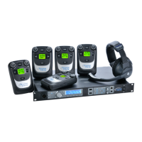
User Guide| FreeSpeak II for Eclipse HX
More information on checking coverage areas is given later in this chapter, in sections:
l Determining coverage areas on page 79 Determining coverage areas on page 79
l Doing a site survey to determine coverage areas on page 81 Doing a site survey to
determine coverage areas on page 81
Consider the following:
l What areas will have more than five active beltpack users in them at any time? Co-locate a
second transceiver there.
l Is there a central place to locate a transceiver so that it will provide omnidirectional (all
directions / circular) coverage?
l Are there balcony areas, corridors, or other rooms or areas that will require coverage with
transceivers?
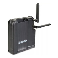
For systems with up to eight transceiver/transceivers, the cable runs will go directly from the
transceiver ports on the rear of the E-Que card. If you need more transceiver/transceivers you will
need to decide where the splitters that feed these will be located.
The E-Que card supports two splitters. Each splitter supports up to 5 transceiver/transceivers
which in turn support up to 5 beltpacks.
For transceiver coverage options see Determining coverage areas on page 79 in this chapter.
7.5.1 Wiring the transceivers and splitters
Note: You can only use the FS II splitter with FS II transceivers that connect to an E-Que card. You
cannot use the splitter with the FreeSpeak II IP Transceiver.
To wire transceivers and splitters:
1. Make sure that the local power supplies are plugged into the transceivers and splitters.
2. Run 4-pair shielded Ethernet cable from the matrix (the E-Que card) to the transceiver or
splitter, and determine that the transceiver or splitter is showing both power (green) and signal
(amber) LEDs. If the amber data LED flashes, a data link is established, and if the LED is
solid, DECT synchronization is established and the system is ready to use.
The E-Que card will not provide power to the transceivers or splitters.
During the initial system setup, before walking through the system with a beltpack to check for
gaps in coverage, it is wise to avoid “permanently” installing the transceiver/transceivers. Hold
them in place in some temporary way until their optimal position is determined.
Note: 4-pair shielded Ethernet cable (CAT-5/5e/6) with RJ-45 connectors on each end is specified for
connection between the matrix and the transceiver/transceivers. Use of other cable can result in
markedly shorter distances of cable runs and other possibly other performance problems.
Page 78
 Loading...
