69 750-265
Serial transmission mode on the Global Modbus network is
RTU mode. Message format has the following characteristics::
The CB Falcon Global Modbus interface supports the following
function codes:
• 03 (0x03) Read Holding Registers
• 06 (0x06) Write Single Register
• 16 (0x10) Write Multiple Registers
• 17 (0x11) Report Slave ID
All of the configuration and status data are accessed as 16-bit
holding registers in this interface. Since all CB Falcon digital
signals accessed in this interface are read-only, these digital
signals are mapped to bits within holding registers instead of
coils or discrete inputs to simplify the interface. Variable length
data are also represented by holding registers, and therefore,
must be accessed individually and not as part of a group. The
length of the variable length data is returned in the response.
All 32-bit data items are accessed as two consecutive 16-bit
holding registers, i.e., each item uses 2 register address
spaces.
The holding register map is defined in the following table.
Except for variable length data items the registers can be
accessed as a single register or up to 20 registers for writes
and 125 registers for reads. Data is mapped into logical
groups with room for future expansion so some gaps exist in
the register map.
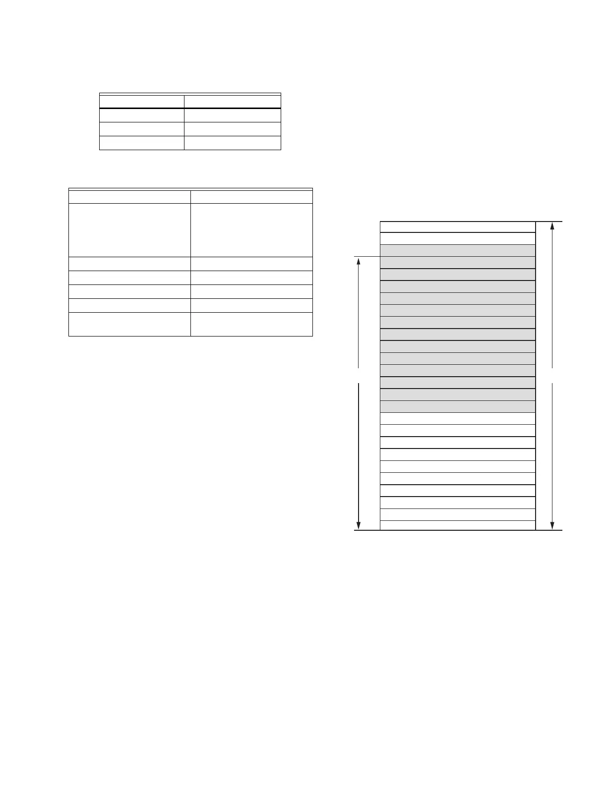
Data organization is intended to allow for efficient register
access. Status data is organized into register blocks by
application function and a function status change indicator is
used to denote when any data has changed within the register
block since the last time the registers were read (see the
following figure). The CB Falcon sets the status change indicator
bit when at least one of the registers in the functional block
has changed value since it was last read. The Global Modbus
master can read the status change register and determine
which functional register blocks have changed value since it’s
last access and only read those register blocks. The Global
Modbus master can ignore the status change register and poll
status data as it deems fit.
Fig. 25. Register map.
Table 32. RS-485 Signals.
Signal Terminal
Data + (a) 1
Data - (b) 2
Common (c) 3
Coding system 8-bit binary
Number of data bits per
character
10 =
1 start bit
8 data bits
No parity bit
1 stop bit
Bit transfer rate 38400 bps
Duplex Half duplex
Error checking 2 byte CRC-16 polynomial
Bit transfer order LSB first
End of message Idle line for 3.5 or more
characters
M28108
SYSTEM STATUS
TREND STATUS
BURNER CONTROL STATUS
SENSOR STATUS
DEMAND & MODULATION STATUS
CENTRAL HEAT (CH) STATUS
DOMESTIC HOT WATER (DHW) STATUS
PUMP STATUS
STATISTICS
LEAD LAG STATUS
SYSTEM CONFIGURATION
MODULATION CONFIGURATION
CENTRAL HEAT (CH) CONFIGURATION
PUBLIC
BURNER CONTROL CONFIGURATION
FAN CONFIGURATION
PUMP CONFIGURATION
ANNUNCIATION CONFIGURATION
DOMESTIC HOT WATER (DHW) CONFIGURATION
LIMITS CONFIGURATION
ANTICONDENSATION CONFIGURATION
OUTDOOR RESET (ODR) CONFIGURATION
FROST PROTECTION CONFIGURATION
LEAD LAG CONFIGURATION
SAFETY CONFIGURATION
LOCKOUT HISTORY
ALERT LOG
PIM PUBLIC