99 750-265
8. Write 0 (Download) to Transfer Direction register. This
write starts actual download to begin (Transfer Status
register should change to transfer in progress).
9. Read Transfer Status register until status indicates
transfer is complete (or failed).
10. Repeat steps 2-8 for next block of data.
The procedure to transfer data from the CB Falcon is:
1. Ensure that no transfer is currently in progress by the
Falcon (look at Transfer Status). If so, cancel the trans-
fer or wait.
2. Write source address for first byte in Falcon into Trans-
fer Base Address register.
3. Write total number of bytes to transfer into Transfer Size
register (number must be less than 33).
4. Write data type into Transfer Type register.
5. Write 1 (Upload) to Transfer Direction register. This
write starts actual upload to begin (Transfer Status reg-
ister should change to transfer in progress).
6. Read Transfer Status register until status indicates
transfer is complete (or failed).
7. Read Transfer Size register to get the actual number of
data bytes transferred by the Falcon. Fewer data bytes
may transfer than requested (end of block).
8. Read all Transfer Data registers starting with first one
(address 0x2005) until enough have been read to get
number of bytes transferred.
PARAMETER CONTROL BLOCK (PCB)
Parameter Control Block (PCB) files are used in the Falcon
to customize the interface that the user has with the Falcon.
Several PCB file types are defined for different customization
purposes. The PCB files are maintained outside of the Falcon
and transferred to the Falcon using the download
procedure defined above. The PCB files can be retrieved from
the Falcon using the upload procedure defined above.
Each PCB specifies attributes for the public Modbus holding
registers. These attributes differ from actually specifying the
value of the registers, i.e., configuration parameter settings,
but instead define how the register is used in the Falcon
installation. These same attributes are uploaded into the Local
and System displays when they initially communicate with the
CB Falcon.
NOTE: Not all registers in the Modbus register map (see
Table 33) are included in the PCB “public” register
context. The status and configuration parameter reg-
isters from the beginning of the register map up to
the end of the Lead Lag configuration group are
within the PCB public context. Registers defined
above them, e.g., Lockout History, Alert Log, etc., are
outside the context of PCB files.
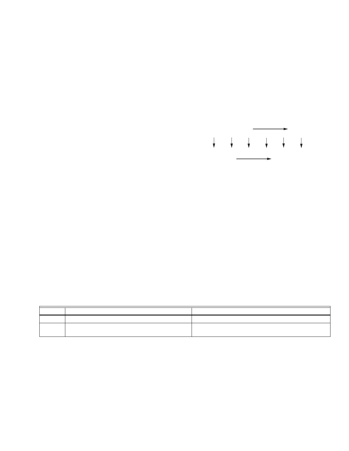
The PCB files are downloaded and uploaded using the Global
Modbus block data transfer procedure. A PCB file is
transferred in blocks up to 32 bytes at a time. For example,
see Fig. 27.
Fig. 27. PCB data transfer.
The PCB data is written to the Transfer Data registers, the
number of bytes written is written into the Transfer Size
register, and the relative byte offset into the PCB file is written
into the Transfer Base Address register. The Falcon adds the
byte offset onto an internal base address where it places the
PCB file. A download data command is written into the
Transfer Direction register to begin the PCB data transfer.
Once the transfer is complete the next block in the PCB file is
transferred until the complete PCB file is transferred.
TROUBLESHOOTING
To support the recommended Troubleshooting, the Falcon has
an Alert File. Review the Alert history for possible trends that
may have been occurring prior to the actual Lockout.
M28110
PCB DATA (BYTE OFFSET)
TRANSFER DATA
...
2005H
0
2005L
1
2006H
2
2006L
3
2007H
4
2007L
5
Table 45. Fault Code and Troubleshooting.
Code Description Recommended Troubleshooting of Lockout Codes
0None
1 Unconfigured safety data 1. Setup error, return to program mode and recheck.
2. If fault repeats, replace module.