833-3577 CB-FALCON SYSTEM OPERATOR INTERFACE
750-241 19 65-0296—01
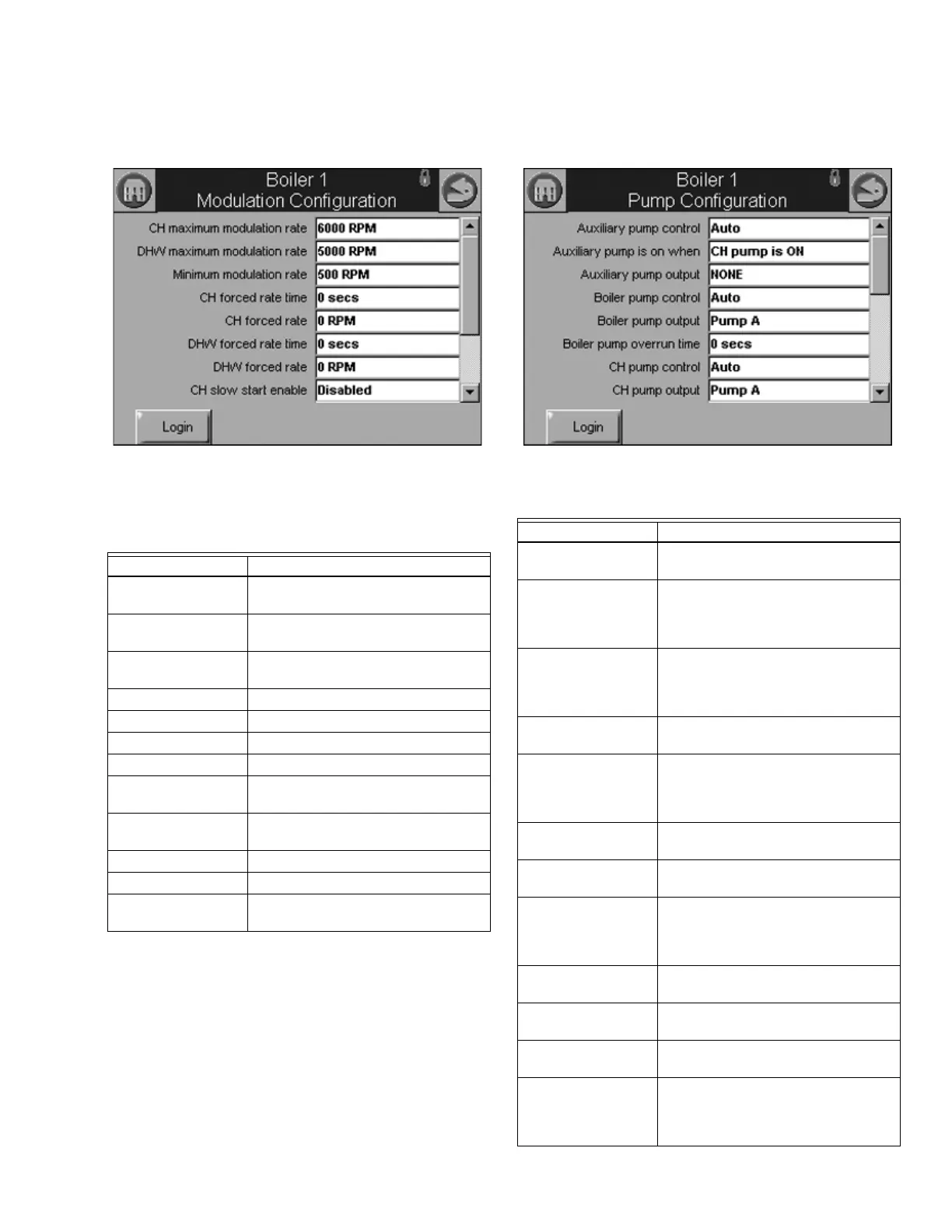
Modulation Configuration Parameters
Table 9 displays Modulation configuration parameters.
Fig. 36. Modulation configuration.
Pump Configuration Parameters
Table 10 displays Pump configuration parameters.
Fig. 37. Pump configuration.
Table 9. Modulation
Configuration Parameters.
Parameter Comment
CH maximum
modulation rate
RPM or %
DHW maximum
modulation rate
RPM or %
Minimum modulation
rate
RPM or %
CH forced rate time 0-600 seconds
CH forced rate RPM or %
DHW forced rate time 0-600 seconds
DHW forced rate RPM or %
CH slow start enable Enabled
Disabled
DHW slow start
enable
Enabled
Disabled
Slow start degrees -40 °C - 130 °C (-40 °F - 266 °F)
Slow Start Ramp RPM /minute or %/minute
0-10/4-20 mAOutput
hysteresis
Table 10. Pump Configuration Parameters.
Parameter Comment
Auxiliary pump
control
Auto
On
Auxiliary pump is on
when
CH pump is ON
DHW pump is ON
CH or DHW pump is ON
Slave command
Auxiliary pump output Pump A
Pump B
Pump C
None
Boiler pump control Auto
On
Boiler pump output Pump A
Pump B
Pump C
None
Boiler pump overrun
time
0-600 seconds
0 = Not configured
CH pump control Auto
On
CH pump output Pump A
Pump B
Pump C
None
CH pump overrun
time
0-600 seconds
0 = Not configured
CH pump frost
overrun time
0-600 seconds
0 = Not configured
DHW pump control Auto
On
DHW pump output Pump A
Pump B
Pump C
None