833-3577 CB-FALCON SYSTEM OPERATOR INTERFACE
750-241 41 65-0296—01
“On” status is indicated by a green LED and “Off” status is
indicated by a red LED.
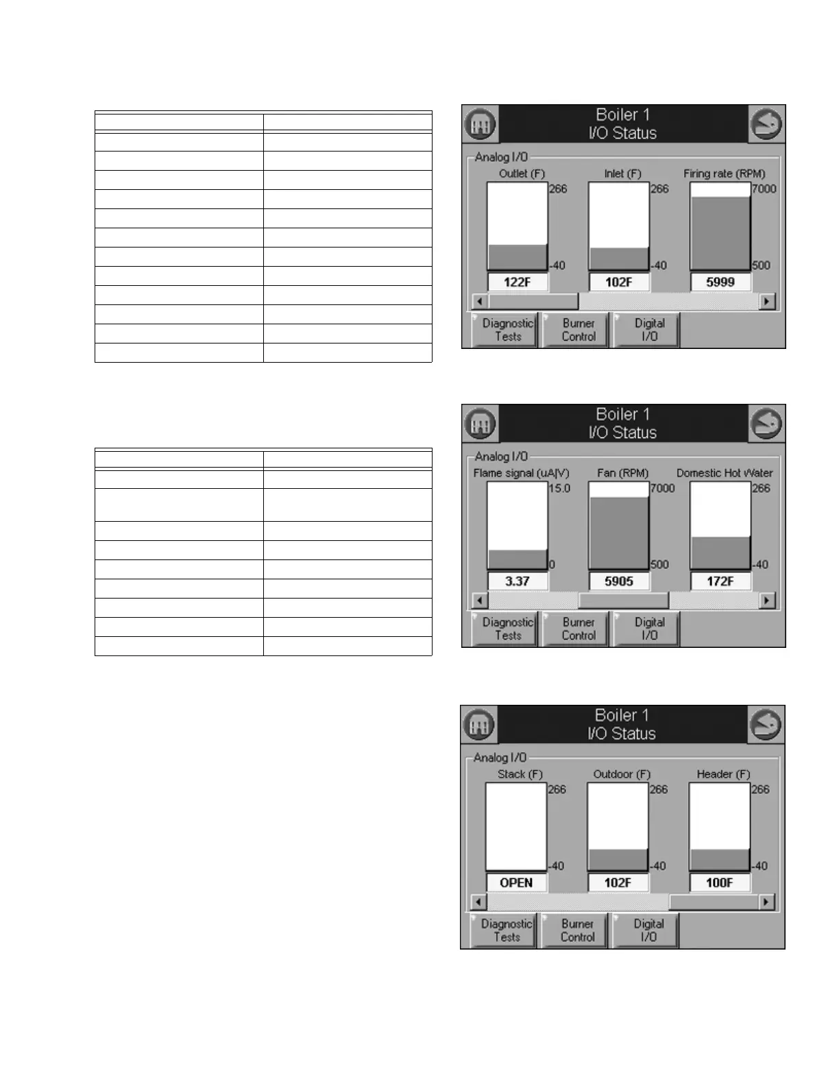
Analog I/O data is displayed as bar charts depicting the I/O
level (see Fig. 101). Analog I/O that is not enabled for the
installation displays a blank I/O level. To see all analog I/O,
use the horizontal scroll bar to move the view left and right.
Fig. 101. Diagnostics analog I/O page (left).
Fig. 102. Diagnostics analog I/O page (center).
Fig. 103. Diagnostics analog I/O page (right).
Load Control Input On/Off
STAT On/Off
Pre-ignition interlock On/Off
Interlock On/Off
Time Of Day On/Off
Annunciator 1-6 On/Off
High Fire/Annunciator 7 On/Off
Low Fire/Annunciator 8 On/Off
Reset switch On/Off
Pilot test hold On/Off
DHW limit On/Off
PM None/Installed
Table 41. 833-3639 Analog I/O Data.
Data Comment
Firing rate % or RPM
Fan speed RPM (if applicable). Should
match with firing rate.
Flame signal V
Header temperature If enabled
Outlet temperature
Inlet temperature If enabled
DHW temperature If enabled
Stack temperature If enabled
Outdoor temperature If enabled
Table 40. 833-3639 Digital I/O Data.
Data Comment