4
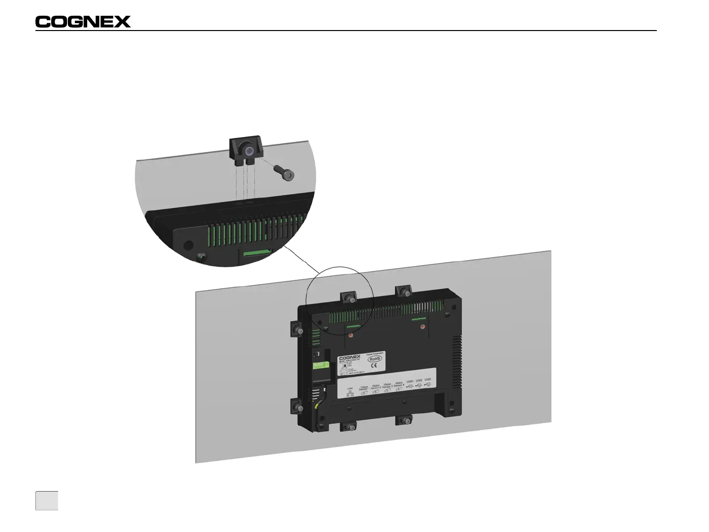
5. Insert an M4 set screw into a mounting clip and tighten the screw until it is partially threaded in the mounting clip.
6. Insert the mounting clip into one of the 8 insertion points located on the perimeter of the display.
7. Holding the mounting clip firmly in place, tighten the set screw using a 3mm hex wrench; maximum torque 0.2259 Nm (2 in-lb). Repeat
for the 7 remaining set screws and mounting clips until VisionView is securely attached to the panel, ensuring the rubber gasket
remains in place. If properly mounted, less than 1.5mm of the rubber gasket should be visible around the front perimeter of the
VisionView display.
Figure 2-2: Insert Mounting Clips and Screws