InteliLite 9 Global Guide
34
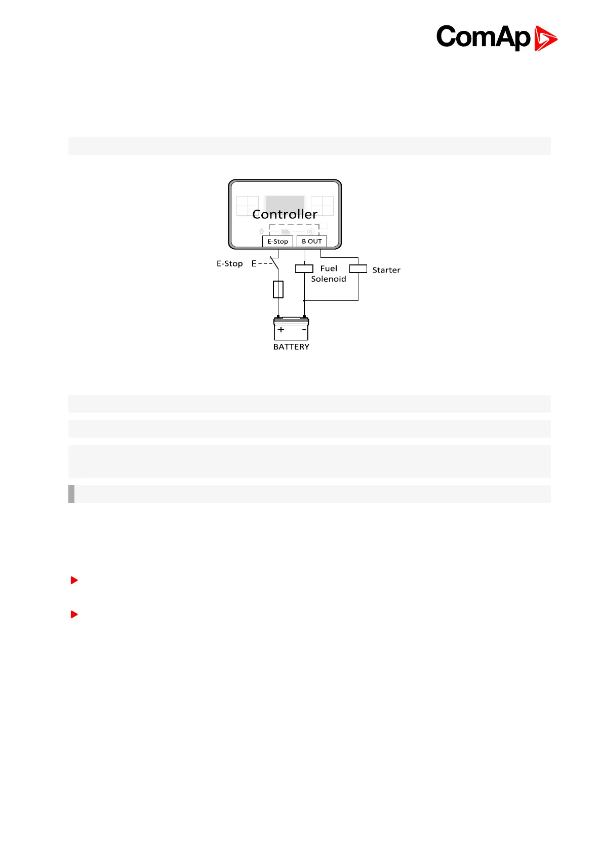
4.4.8 E-Stop
E stop has dedicated terminal T09. Power supply of binary output 1 and binary output 2 (terminals 4 and 5) is
internally connected (in controller) to E-Stop terminal. It means higher security and faster disconnection of these
outputs. More information about E-Stop functions see E-Stop on page 109.
Note: This function has the same behavior as binary input EMERGENCY STOP (PAGE 305).
Image 4.15 E-Stop wiring
Note: Recommended fusing is 12 A fuse.
Note: Grey dashed line symbolizes internal connection between E-Stop and binary outputs 1 and 2.
Note: For proper functionality of E-Stop, the terminal T09 must be always wired. Terminal can be connected to
battery+ or to terminal T03 (BATT+)
IMPORTANT: Suppression diodes are not indicated, but required.
4.4.9 Analog inputs
The analog inputs are designed for resistive automotive type sensors like VDO or DATCON. The sensors are
connected either by one wire (the second pole is the sensor body) or by two wires.
In the case of grounded sensors, connect the AI COM terminal to the engine body as near to the sensors as
possible.
In the case of isolated sensors, connect the AI COM terminal to the negative power supply terminal of the
controller as well as one pole of each sensor.