InteliLite 9 Global Guide
38
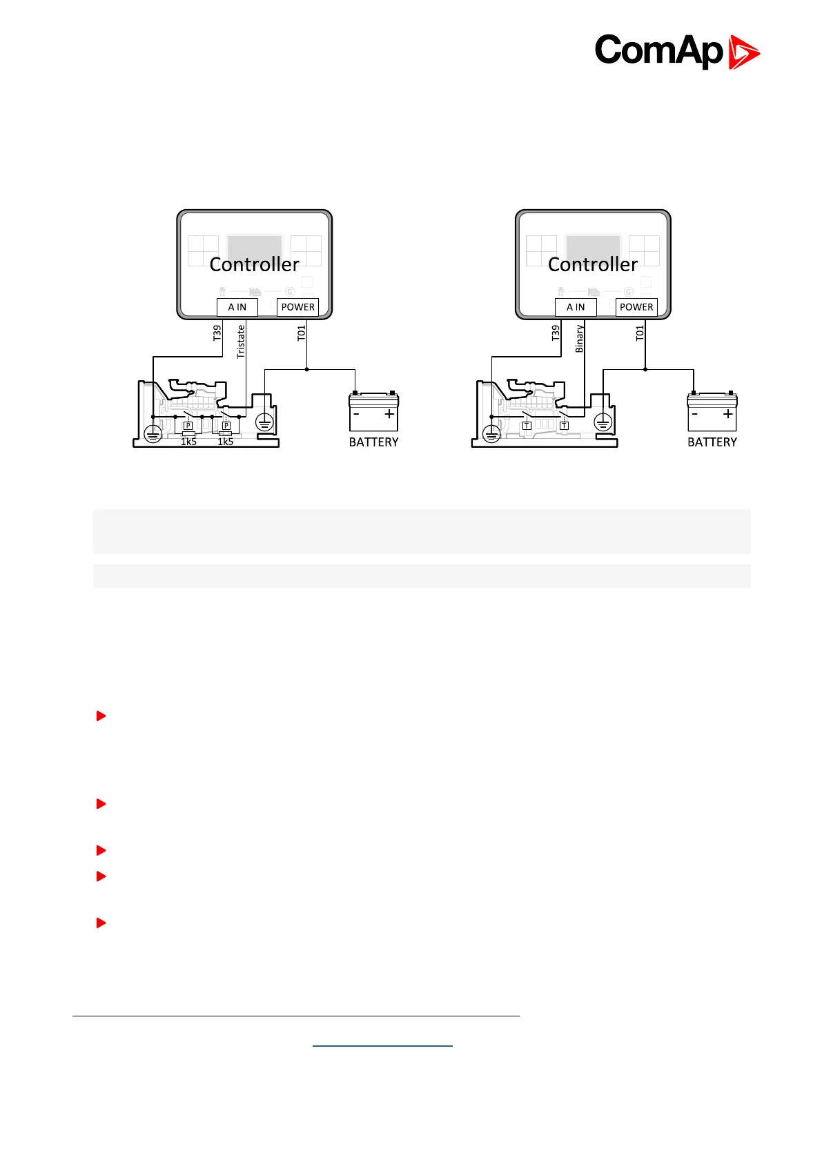
Analog as binary or tristate inputs
Analog inputs can be used also as binary or tri-state, i.e. for contact sensors without or with circuit check. The
threshold level is 750Ω. In the case of tri-state, values lower than 10Ω and values over 2400Ω are evaluated as
sensor failure (short or open circuit).
Image 4.20 Analog inputs as tristate Image 4.21 Analog inputs as binary
Note: The name, sensor characteristic and alarm types for each analog input have to be assigned during
configuration.
Note: Tristate and binary sensors are not suitable for Analog Switch functions.
4.4.10 CAN bus
CAN bus wiring
The wiring of the CAN bus should be provided in such a way that the following rules are observed:
The maximum length of the CAN bus depends on the communication speed. For a speed of 250 kbps, which
is used on the CAN1 bus (extension modules, ECU) and CAN2 bus if it is switched to 32C mode, the
maximum length is 200 m. If the CAN2 bus is switched to 8C mode the speed is 50 kbps and the maximum
length is 800 m.
The bus must be wired in linear form with termination resistors at both ends. No nodes are allowed except on
the controller terminals.
Shielded cable
1
has to be used, shielding has to be connected to the terminal T01 (BATT -).
External units can be connected on the CAN bus line in any order, but keeping line arrangement (no tails, no
star) is necessary.
The CAN bus has to be terminated by 120 Ohm resistors at both ends use a cable with following
parameters:
1
Recommended data cables: BELDEN (http://www.belden.com) - for shorter distances: 3105A Paired - EIA
Industrial RS-485 PLTC/CM (1x2 conductors); for longer distances: 3106A Paired - EIA Industrial RS-485
PLTC/CM (1x2+1 conductors)