Chapter 4 Drive System Wiring And Introduction
mode) and non-position
mode ,please connect 24 V to pin
7, DI5 to pin21, DI6 to pin 22. Or
to connect 0 V to pin7, DI5 to 5
pin ,DI6 to pin 6.
In position mode
(internal position
mode) and
non-position
mode
Common end of
digital input
signals
Photo isolation output.Function can
be programmable.
Defined by parameter F3 group
( F3-20~F3-23).
Note: when FA104 is set to 1,
F3-24 can be a programmable
differential output.
Internal isolated 24V power
output and the voltage range is
20V~28V and max output
current 100mA。
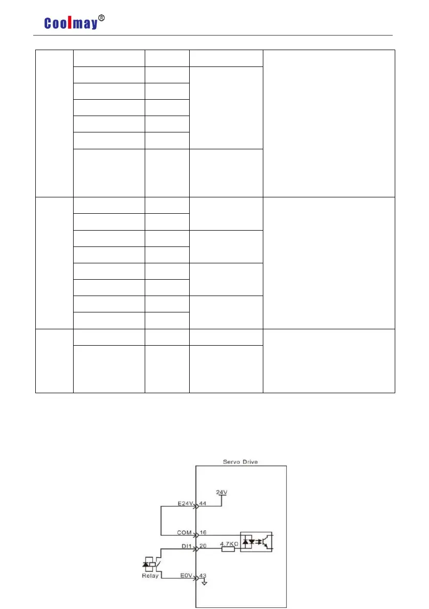
Input Circuit Of Digital Quantity Diagram
For DI1 as an example( the DI1~DI4 interface circuit is the same):
1) When the upper device is relay output: