5-INSTALLATION 5-3
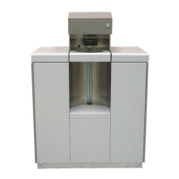
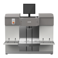
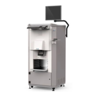
COROB™ TATOCOLOR
COROB™ TATOCOLOR with sliding Autocap
– Position the manual shelf at the right height so as to bring the can, to be lately placed on
the shelf surface, at the proper position in relation to the nozzles (chapter 7.2.1 or 7.3.1).
The can should be positioned so as not to interfere with the opening movement of the
sliding Autocap.
– Place a can onto the shelf making sure that it is properly positioned in relation to the
nozzles.
The can must have an adequate capacity, at least enough to contain the amount of colorant
dispensed during purging, taking into account the number of circuits and the duration of the
purge process.
4. Purge the circuits using the "CorobSERVICE" program.
5. Stop the purge only when the colorant flowing out of the nozzle center is perfectly clean.
5.4.2 Colorant recirculation procedure
After purging the machine, all of the canisters and part of the dispensing circuits have been filled.
It is therefore essential to recirculate the colorant to fill the return segment to the canister; this
procedure will also remove the air emulsified with the colorant while filling the canisters.
1. Activate the recirculation process using the "CorobSERVICE" program.
2. Lift the canister section covers and check in each canister to make sure the colorant returns
through the recirculation connector.
3. When the colorant begins to enter the canisters through the recirculation connectors, stop the
process.
4. Close each canister with its corresponding lid, and close the section covers.
5. Shut off the machine and unplug the power supply cable from the socket outlet (chapter 6.4).
You may now disconnect the service computer (chapter 9).
5.5 Connecting the computer and installing the software
The structure of the dispenser has been designed to connect to a personal computer chosen by
the customer, whose minimum requirements are listed in chapter 3.6.
We recommend that this connection be carried out by personnel skilled with computers.
To connect your computer to the machine, it is possible to use the RS232 serial cable provided
in the packing.
The USB interface cable is no standard equipment, therefore you will have to purchase one
suitable for the connection with the dispenser.
For any information on the computer, refer to the corresponding user’s manual.
The area dedicated to housing the machine management computer, monitor and keyboard is the
upper surface of the dispensing section. The computer can be placed on the adjustable support
plate available as an optional accessory.
The machine has auxiliary sockets on the rear door with the exclusive purpose to power the
computer and all peripheral equipment such as label printer or calibration scale (chapter 6.2).
The auxiliary sockets are powered when the machine main switch is switched on (chapter 6.2).
To power up the computer use the power cords provided in the packing (chapter 4.4).
1. Position the computer.