User’s Manual
11
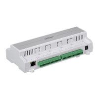
Table 2-1 Function
No. Name Function
1 DIP switch Restores to the factory settings.
2 Network port Connects to Ethernet port.
3 LINK indicator Network indicator.
4 ACTIVE indicator Network indicator.
5
Z1–Z8 Zone 1–Zone 8.
G Ground.
6
+12V Auxiliary power output 12 VDC with 1000 mA.
G Ground.
7
ST Tamper port, and generally used as siren tamper.
G Ground.
SIREN Connects to siren.
8 NC, COM, NO
Relay port. The maximum touch point load is 0.5 A, 125 VAC/1
A, 30 VDC.
9
OUT_1, OUT_2 Alarm output driven by MOS.
G Ground.
10
VBAT
Positive pole and negative pole of battery. The negative pole
must receive ground connection.
G Ground.
11 TIP_O, RING_O Telephone connection port.
12 TIP_IN, RING_IN Telephone line port.
13 OUT_1 indicator
ON: OUT_1 is open.
OFF: OUT_1 is closed.
14 OUT_2 indicator
ON: OUT_2 is open.
OFF: OUT_2 is closed.
15 BUS2_TX indicator
Data transmitting indicator of the second group of RS-485
ports.
ON: Transmitting is in process.
16 BUS2_RX indicator
Data receiving indicator of the second group of RS-485 ports.
ON: Date receiving is in process.
17 BUS1_TX indicator
Data transmitting indicator of the first group of RS-485 ports.
ON: Transmitting is in process.
18 BUS1_RX indicator
Data receiving indicator of the first group of RS-485 ports.
ON: Date receiving is in process.
19 A2, B2 Connects to RS-485 expansion module.
20
+12V
Auxiliary power output 12 VDC supplies power to the external
devices such as detectors.
G Ground.
21 A1, B1 RS-485 port that connects to keypad (maximum 8 Keypads).
 Loading...