User’s Manual
21
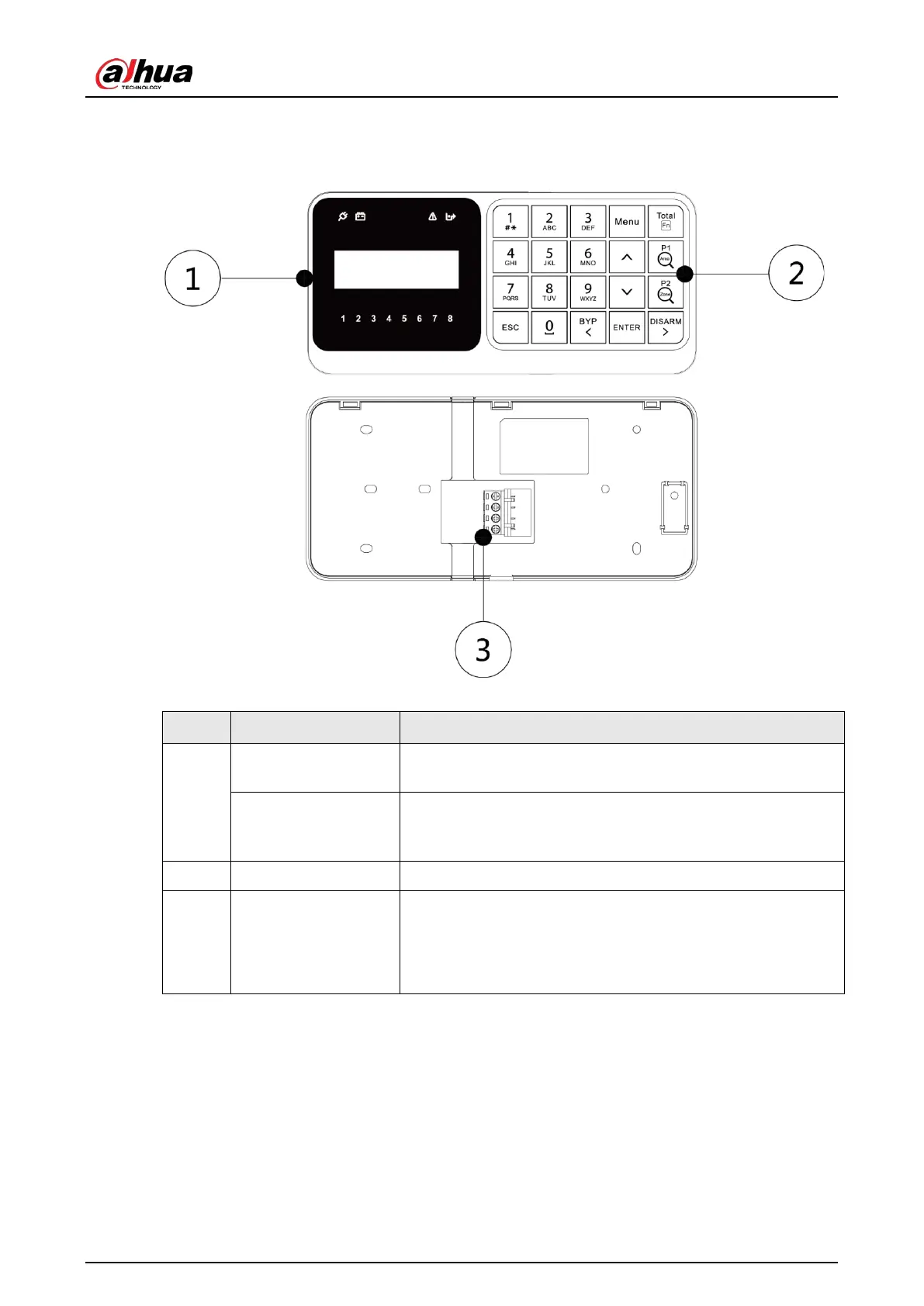
4.4 Structure
Figure 4-4 Structure
Table 4-1 Function
No. Name Function
1
LCD display
Displays all the system information including management
and programming. For details, see "4.7 LCD Display".
LED indicators
Displays information about power status, battery status,
failures, bypass, and alarm status of each area. For details, see
"4.6 LED Indicators".
2 Keys Each key has specific function. For details, see "4.5 Keys".
3 Ports
●
+12V: Supplies 12 VDC.
●
GND: Ground.
●
RS485_A1
●
RS485_B1
4.5 Keys
Each key of the keypad has a specific function.
 Loading...